


Riva Plus Manual
30
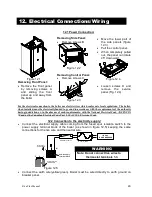
12.3 Room Thermostat Connection:
•
The room thermostat
must be connected to
the
terminal
block
situated next to the
control panel.
1
2
L
N
3
To fused spur
isolation switch
Power supply
terminal block
External controls
terminal block
J
120 VAC Control
Terminal Block
Figure 12.6
•
Any external controls
and connection lines
must be rated at 120
VAC but under no
circumstances should
external live voltage
be connected to the
room thermostat link
on the boiler.
•
When connecting any
type
of
external
control, the jumper J
in Fig. 12.6 must be
removed.
•
The room thermostat
must be connected to
the “Control Terminal
Block” (Fig 12.7).
•
•
Connect
the
room
thermostat
between
terminals 1 and 3 as
shown in Fig. 12.7.
Power supply
terminal block
External controls
terminal block
T
Room thermostat
1
2
L
N
3
(120V rating)
Figure 12.7
12.4 Relay Panel Connection:
•
The relay control must
be connected to the
terminal block situated
next to the control
panel.
1
2
L
N
3
To fused spur
isolation switch
Power supply
terminal block
External controls
terminal block
J
120 VAC Control
Terminal Block
Figure 12.8
•
When connecting any
type of relay control,
the jumper J in Fig.
12.8 must be removed.
•
Connect
the
dry
contact switch of the
relay panel to the 120
VAC control terminal
block (Fig 12.9).
•
•
Connect
the
dry
contact
switch
to
terminals 1 and 3
shown in Fig. 12.9.
Power supply
terminal block
External controls
terminal block
Generic Relay Control
1
2
L
N
3
(120V rating)
T
Figure 12.9
12. Electrical Connections/Wiring Cont.
Summary of Contents for Riva Plus
Page 2: ...Riva Plus Manual 2...
Page 14: ...Riva Plus Manual 14 5 1 Sequence of Operation...
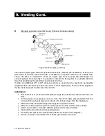
Page 20: ...Riva Plus Manual 20 9 Venting Cont...
Page 50: ...Riva Plus Manual 50...


