


Riva Plus Manual
29
12.1 Power Connection:
A
A
Figure 12.1
Removing Front Panel:
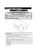
•
Remove the front panel
by removing screws A
and sliding the front
panel up and away from
the boiler.
Removing Side Panel:
•
Remove screws B
B
B
C
C
B
B
Figure 12.2
Removing Control Panel:
•
Remove screws C.
Figure 12.3
•
Move the lower part of
the side panels (figure
12.3).
•
Pull the control panel.
•
When completely pulled
out, the panel can rotate
45° downward.
D
D
D
Figure 12.4
•
Loosen screws D and
remove
the
service
panel (Fig. 12.4)
For the electrical connection to the boiler use electric wires which conform to local regulations.
The boiler,
when installed, must be electricallybonded to ground in accordance with the requirements of the authority
having jurisdiction or, in the absence of such requirements, with the
National Electrical Code, ANSI/NFPA
70
and/or the Canadian Electrical Code Part I,
CSA C22.1, Electrical Code
.
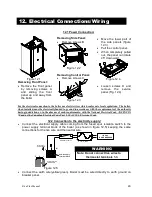
12.2 Connection to the electricity supply:
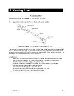
•
Connect the electrical supply cable coming from the fused spur isolation switch to the
power supply terminal block of the boiler (as shown in figure 12.5) keeping the same
connections for the live wire and the neutral wire.
1
2
L
N
3
To fused spur
isolation switch
Power supply
terminal block
External controls
terminal block
120 VAC
15 AMP BREAKER
Service Man's Switch
Fire - O - Matic
Figure 12.5
•
Connect the earth wire(yellow/green). Boiler must be wired directly to earth ground on
breaker panel.
12. Electrical Connections/Wiring
Note: Do not connect live wires to
thermostat terminals 1-3.
WARNING
Summary of Contents for Riva Plus
Page 2: ...Riva Plus Manual 2...
Page 14: ...Riva Plus Manual 14 5 1 Sequence of Operation...
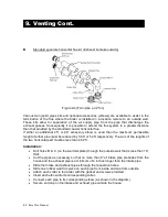
Page 20: ...Riva Plus Manual 20 9 Venting Cont...
Page 50: ...Riva Plus Manual 50...


