Biasi Riva ADVANCE SV Owner'S Manual Download Page 12

12  RIVA ADVANCE USER MANUAL

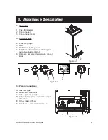
5.  Instructions For Use
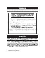
5.1 Warnings:

•  In order to guaranty safety and correct operation, it is essential that all the tests are carried 

out by a competent and responsible licensed service person before lighting up the boiler.

•  The tests are described in the installation, operation and service instructions manual in Sec-

tion 15 Commissioning.

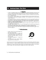
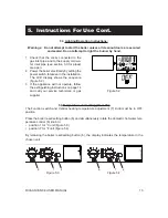
•  Ensure that the Central Heating circuit is regularly filled with water checking that the pres-

sure indicated on the pressure gauge (4 on figure 3.2) is not lower than 1 bar (14.5 psi) as 

shown on figure 5.1.

•  If the pressure reading on the pressure gauge is below 1 bar (14.5 psi), then the system will 

require filling. An automatic filling valve is normally provided by the installer for this purpose.

•  If you are in any doubt regarding this procedure you are advised to contact your In-

staller or an Approved Service Person.

•  This appliance is provided with a built in anti-freeze system that operates the boiler when 

the temperature is below 41 °F.

•  Therefore, when the boiler is not lit or used in cold weather, with consequent risk of freezing 

do not switch off the boiler at the circuit breaker or close the gas inlet cock.

•  When you expect not to use the boiler for a long period follow the instructions given in sec-

tion 5.6 on page 15.

5.2 Refilling procedure:

•  Isolate the boiler from the electrical sup-

ply at the circuit breaker.

•  The boiler should have been installed with 

an automatic fill valve, external to the unit. 

Open the cold water supply to the auto-

matic fill valve.

•  The pressure should be 1 – 1,5 bar (14.5 

– 22 psi).

•  The  automatic  fill  valve  should  maintain 

this pressure, but not exceed it.


Figure 5.1 

Air introduced into the boiler during this filling process will vent through the automatic air purger 

fitted to the boiler. You may also find it necessary to vent air from your heating circuit using the 

installed vents, however be aware that excessive venting will cause the pressure in the system 

to drop. Always ensure that the pressure gauge is set at the required pressure.

Summary of Contents for Riva ADVANCE SV

Page 1: ...use any phone in your building Immediately call your gas supplier from a neighbor s phone Fol low the gas supplier s instructions If you can not reach your gas supplier call the fire department Instal...

Page 2: ...equipment that comes with every devices supplied with every boiler is absolutely necessary to the safe operation of the boiler and protection of the heating system All BIASI wall hung boilers are bui...

Page 3: ...CD General Features 4 10 11 Instructions for Use 5 12 17 Warnings 5 1 12 Refilling Procedure 5 2 12 Lighting Operating Instructions 5 3 13 Temperature Unit Setting C or F 5 4 13 Central Heating Circui...

Page 4: ...ified service technician to inspect the boiler and to replace any part of the control system and any gas control which has been under water Do not store or use gasoline or other flammable vapors and l...

Page 5: ...n confused with those of influenza and the highest incidence of poisoning occurs at the onset of cold weather or during flu season A victim may not experience any symptoms only one symptom or a few sy...

Page 6: ...an and free of all fire hazards Please read the literature and warranties supplied by the manufacturers of the various accessory equipment This equipment is warranted by the respective manufacturers n...

Page 7: ...ion system to prevent frost dam age which can occur in areas susceptible to very cold weather conditions Boiler operation recognition system should the boiler not be used for longer than 24 hours it t...

Page 8: ...2 25 4 3 25 5 Twin split pipes in 3 25 3 25 Nominal heat flow rate 0 2000 ft MBH 125 0 Nominal heat flow rate 2000 4500 ft MBH 112 5 Max Exhaust temperature F 190 GAS FLOW RATE Gas Min Max Natural ft...

Page 9: ...tton 7 Function switch and Central heating tem perature adjustment knob 8 Domestic hot water temperature control knob 4 5 6 7 8 bar 3 1 2 H Figure 3 1 Figure 3 3 Figure 3 2 3 3 Piping Connections A Ga...

Page 10: ...at intervention lockout E03 General lockout E10 Flue probe intervention lockout E11 Flame detection error E04 Faulty primary circuit no water or absence of flow E05 Faulty fan control system E06 Fault...

Page 11: ...ar Pump operating C Variable temperature expressed in C bar Variable expressed in bar if the pressure sensor is installed Set D h w visible for 10 sec all other symbols are disabled symbol flashing 35...

Page 12: ...uilt in anti freeze system that operates the boiler when the temperature is below 41 F Therefore when the boiler is not lit or used in cold weather with consequent risk of freezing do not switch off t...

Page 13: ...n The LCD display shows the sequence figure 5 2 3 If the appliance will not operate follow the extinguishing instructions on page 14 and call your service technician or gas supplier Figure 5 2 5 4 Tem...

Page 14: ...rature al ters the gas flow at the burner according to the thermal demand in the system So it is usual to see the burner lit at the mini mum level for more or less long periods 5 Adjustment of central...

Page 15: ...he most suitable adjustment for your system The LCD indicates if the set temperature has been reached Request for heating power If the boiler requests heating power you can see the sequence on the LCD...

Page 16: ...temperature of the domestic hot water contained in the tank can be adjusted to a maximum of approx 140 F turning the boil er setting knob indicated in Figure 5 11 If there is a large amount of limest...

Page 17: ...e external temperature may be lower than 32 F it is suggested to leave the system running setting the room thermostat at a low temperature When the boiler is completely switched off for a long period...

Page 18: ...the reset button 6 Figure 6 2 on the boiler control panel Signal given by the LCD display Figure 6 3 For the first light up and following main tenance procedures for the gas supply it may be necessary...

Page 19: ...not happen and to decrease the pressure to a normal value it is advisable to vent some of the water in the appliance through the bleed valves present in the heating system Figure 6 4 3 1 2 H If water...

Page 20: ...eight pre paid QHT and Biasi will not be responsible for 1 Components that are part of the heating system but were not manufactured by Biasi or QHT as part of the boiler 2 The workmanship of the insta...

Page 21: ...RIVA ADVANCE USER MANUAL 21...

Page 22: ...22 RIVA ADVANCE USER MANUAL...

Page 23: ......

Page 24: ...1796220680 17962 2068 0 2712 24A4 USA 09 07 2012 N...

Reviews: