


- 76 -
INST
ALLA
TION
COMMISSIONING
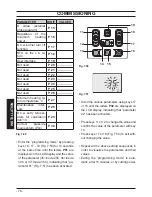
PARAMETER
DIGIT VALUES
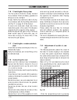
K value (external
probe diagram)
P 15
Regulation of the
minimum heating
power
P 16
D.h.w. burner turn off
function
P 17
NTC on the c.h. re-
turn
P 18
User interface
P 19
Not used
P 20
---------------
Not used
P 21
---------------
Not used
P 22
---------------
Not used
P 23
---------------
Not used
P 24
---------------
Not used
P 25
---------------
Not used
P 26
---------------
Minimum heating re-
turn temperature °C
P 27
Maintenance inter-
vals
P 28
D.h.w. entry temper-
ature for calculation
def=10
P 29
Correct pressure
main system (Pon)
P 30
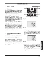
Fig. 7.49
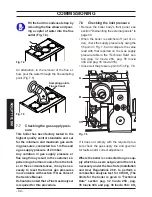
• Enter the ”programming mode” by pressing
keys 14 - 17 - 18 (Fig. 7.50) for 10 seconds
at the same time until the letters
P01
are
displayed on the LCD display and the value
of the parameter (35=Inovia 25C, 36=Inovia
30C or 37=Inovia 35C), indicating that ”pa-
rameter 01” (Fig. 7.51) has been activated.
Fig. 7.50
11
12
13
14 15
16
17
18
19
Fig. 7.51
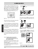
• Scroll the various parameters using keys 17
or 18 until the letters
P02
are displayed on
the LCD display, indicating that ”parameter
02” has been activated.
• Press keys 11 or 12 to change the value and
confirm the value of the parameter with key
14.
• Press keys 17 or 18 (Fig. 7.50) to exit with-
out changing the value.
• Repeat all the above setting sequences in
order to visualize the parameters and their
values.
• Exiting the “programming mode” is auto-
matic, after 15 minutes, or by cutting power.
Summary of Contents for Inovia 25C
Page 90: ...90 NOTES...
Page 91: ......