


- 75 -
INST
ALLA
TION
COMMISSIONING
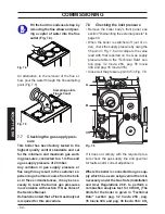
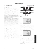
keys 14 - 17 - 18 (Fig. 7.47) for 10 seconds
at the same time until the letters
P01
are
displayed on the LCD display, indicating that
”parameter 01” (Fig. 7.46) has been acti-
vated.
Fig. 7.46
Fig. 7.47
11
12
13
14 15
16
17
18
19
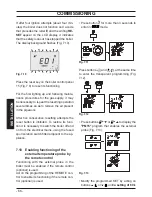
• Scroll the various parameters using keys
17 or 18 until the letters
P12
are displayed
on the LCD display and the value of the pa-
rameter (74=Inovia 25C, 78=Inovia 30C or
84=Inovia 35C), indicating that ”parameter
12” (Fig. 7.48) has been activated.
Fig. 7.48
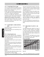
• It is possible to modify parameter using keys
11 or 12 (Fig. 7.47) (Refer to Fig. 7.45 and
determine the correct Value appertaining to
the output required for the central heating
requirement.).
• By pressing key 14 (Fig. 7.47) confirmation
of the inserted value is obtained.
• Press keys 17 or 18 (Fig. 7.47) to exit with-
out changing the value.
• Exiting the “programming mode” is auto-
matic, after 15 minutes, or by cutting power.
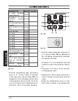
7.20 Setting record
Important: at the end of the setting opera-
tion it is important to fill/update the table
(Fig. 7.49).
This to allow a correct setting of this boiler
in case of replacement of the main control
p.c.b.
PARAMETER
DIGIT VALUES
Boiler type
P 01
Water sensors con-
figuration
P 02
Pump management
P 03
TA/OT zone manage-
ment
P 04
Gas type
P 05
Not used
P 06
---------------
C.h. flow max tem-
perature °C
P 07
Factory parameters
reset
P 08
Chimney
sweep
function
P 09
C.h. reignition fre-
quency
P 10
C.h. pump post-circu-
lation
P 11
Max. useful output in
c.h. mode
P 12
C.h. pump working
type
P 13
Ignition power
P 14
Summary of Contents for Inovia 25C
Page 90: ...90 NOTES...
Page 91: ......