


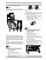


Fan and Air pressure switch
34
N.O.
N.C.
”L” connection
COM
”H” connection
Fig. 69a
”L” connection
”H” connection
Fig. 69b
n
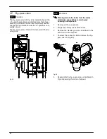
Check of the venturi device
This test must be carried out with the sealed
chamber closed
1
Remove the caps of the pressure test points lo-
cated on the top of the boiler and connect a differ-
ential pressure gauge (Fig. 70).
2
Switch on the boiler.
Fig. 70
3
Compare the value on the gauge with the follow-
ing minimum values:
80 Pa (0,8 mbar) --- M96.24SM/...
110 Pa (1,1 mbar) --- M96.28SM/...
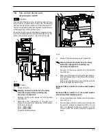
18.3
Removal of the Fan
Warning: isolate the boiler from the mains
electricity supply before removing any
covering or component.
1
Remove all the case panels, the sealed chamber
lid and the combustion chamber lid.
2
Disconnect the connectors
D
and the earth con-
nection
E
(Fig. 68).
3
Disconnect the pipe which connect the venturi
device to the Air pressure switch.
4
Unscrew the screw
F
and remove the bracket
G
(Fig. 71).
D
E
C
F
G
Fig. 71
5
Remove the Fan by sliding it towards left (se the
arrow in Fig. 71).
6
Assemble the fan carrying out the removal oper-
ations in reverse sequence.
Warning: Re--assembling the fan ensure that the
hooks around the inlet port of the fan hung correctly
on the flue hood.
Warning: to correctly connect the venturi device to
the Air pressure switch, refer to Fig. 72.
---
+
Fig. 72
Warning: After cleaning or replacement as
detailed above, if it deemed necessary to
undertake a combustion analysis, refer to
the appropriate chapter
Maintenance
of the
installation instructions manual.


