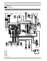


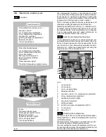


Electronic control p.c.b.
18
If the power requested is lower than 40% of the maxi-
mum power output then control is achieved by switch-
ing ON the burner at minimum power, then switching
OFF (ON/OFF function). If the power requested is
higher, then the burner is switched ON at maximum
power and will control by modulating to 40% of the
maximum power output.
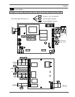
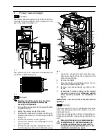
During the c.h. operation (Fig. 30), the signal coming
from the c.h. temperature probe is compared to the sig-
nal given by the control panel through the adjustment
made by the user (knob
). The result of such a
comparison operates the modulation of the gas valve,
consequently changing the useful output of the boiler.
Fig. 30
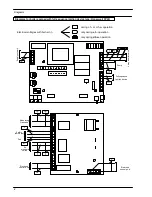
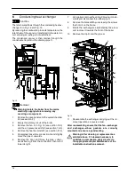
When the boiler functions in d.h.w. (Fig. 31), the signal
coming from the d.h.w. temperature probe is compared
with the signal given by the control panel through the
adjustment made by the user (knob
).
75
°
C
Fig. 31
Normally, the result of the comparison between these
two signals directly operates the adjustment elements
of the gas valve modulation device, adjusting the useful
output generated in order to stabilize the temperature
of the exiting water.
If during the d.h.w. mode operation, the temperature of
the primary circuit goes over 75
°
C, the useful output is
automatically reduced so that the primary circuit can-
not reach excessive temperatures.
The control sequences in
function and in
func-
tion are illustrated in detail in sections 10.10 and 10.11.
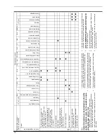
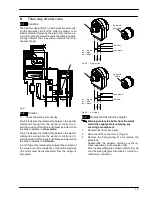
10.4
Operation lights
The Electronic control p.c.b. is provided with three
lamps (L.E.D. indicators) 7 in Fig. 29 that give optical in-
formation during the operation of the boiler.
The green lamp on the left gives information whether
the boiler is in stand---by mode or during the normal
operation of the boiler.
The following table gives the relationship between the
lamp indication and its meaning.


