


11
5
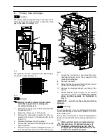
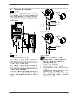
Primary heat exchanger
5.1
Function
The primary heat exchanger
A
in Fig. 9 has the function
of transferring heat produced from combustion of the
gas to the water circulating in it.
A
Fig. 9
The hydraulic circuit is composed of 8 elliptical pipes
connected in parallel (Fig. 10).
Fig. 10
5.2
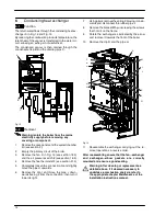
Removal
Warning: isolate the boiler from the mains
electricity supply before removing any
covering or component.
1
Remove the case panels and the sealed chamber
lid (see section 2).
2
Empty the primary circuit of the boiler.
3
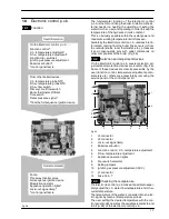
Remove the combustion chamber lid
B
by un-
screwing the screws
C
and removing the clamp
D
(Fig. 11).
4
Remove the screws
E
and the plate
F
.
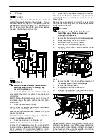
5
Loosen the connection
G
and slightly move the
pipe
H
upwards.
6
Remove the clip
I
and the safety thermostat
J
. It
is not necessary to disconnect it from the wiring.
E
M
C
B
F
C
D
G
I
J
N
K
L
H
Fig. 11
7
Loosen the connection
K
and move the pipe
L
downwards freeing it from the connection of the
primary het exchanger.
8
Remove the clip
M
9
Move the pipe
N
upwards freeing it from the con-
nection and rotate towards right.
10
Remove the heat exchanger by sliding it for-
wards.
11
Reassemble the boiler carrying out the removal
operations in reverse order.
Fit the clip
I
with the
arrow pointing upwards as illustrated in
Fig. 11.
IMPORTANT -- do not force the connection
G
when
tighting it.
5.3
Cleaning
If there are deposits of soot or dirt between the blades
of the heat exchanger, clean with a brush or non---me-
tallic bristle brush.
In any case, avoid any actions that can damage the pro-
tective varnish with which the exchanger has been cov-
ered.
Warning: After cleaning or replacement as
detailed above, if it deemed necessary to
undertake a combustion analysis, refer to
the appropriate chapter
Maintenance
of the
installation instructions manual.


