


33
18
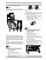
Fan, venturi device and
Air pressure switch
18.1
Function
The function of the Fan
A
(Fig. 67 and Fig. 68) is to force
the products of combustion trough the condensing
heat exchanger to the outside air via the flue system.
The Fan is supplied by the full sequence ignition device
at the beginning of the ignition cycle.
Its correct functioning is controlled by means of a sys-
tem incorporating a built in venturi device (
B
in Fig. 73)
and an Air pressure switch
C
(Fig. 67 and Fig. 68) .
A
C
Fig. 67
18.2
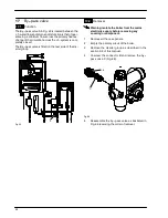
Checks
n
Check of the fan
Warning: isolate the boiler from the mains
electricity supply before removing any
covering or component.
1
Remove all the case panels and the sealed
chamber lid.
2
Disconnect the connectors
D
(Fig. 68) and
measure the electrical resistance of the motor
that has to be about:
43
W
--- M96.24SM/...
25
W
--- M96.28SM/...
(at ambient temperature).
D
A
C
Fig. 68
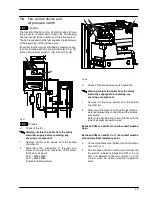
n
Check of the Air pressure switch operation
Warning: isolate the boiler from the mains
electricity supply before removing any
covering or component.
1
Remove all the case panels and the sealed
chamber lid.
2
Disconnect the wires and check the electrical re-
sistance between the connections of the Air pres-
sure switch.
Refer to the Fig. 69a or b in accordance with the
type of air pressure switch used.
Between COM or 3 and N.O. or 2 the contact must be
open.
Between COM or 3 and N.C. or 1 the contact must be
closed (electrical resistance zero).
3
Connect the black wire (COM or 3) and the brown
wire (N.C. or 1).
4
Run the boiler (the Fan must run) and check the
the electric resistance between COM or 3 and
N.O. or 2. Between COM or 3 and N.O. or “2 the
contact must be closed (electrical resistance
zero).


