- 72 -
INST
ALLA
TION
ADVANCED COMMISSIONING
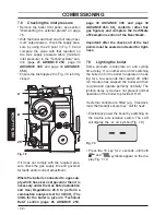
PARAMETER
DIGIT VALUES
C.H. flow max temper
-
ature °C
Pr 07
Factory
parameters
reset
Pr 08
Flue sweep function
Pr 09
C.H.
reignition fre-
quency
Pr 10
C.H. pump post-circu
-
lation
Pr 11
Max. useful output in
C.H. mode
Pr 12
C.H. pump working
type
Pr 13
Ignition power
Pr 14
K value (external
probe diagram)
Pr
15
Not used
Pr 16
D.H.W. burner turn off
function
Pr 17
NTC on the C.H.
return
Pr 18
LCD type
Pr 19
Not used
Pr 20
-----------
Not used
Pr 21
-----------
D.H.W. flow minimum
Pr 22
Not used
Pr 23
-----------
Duty Cycle Zone
Pr 24
C.H. flow temperature
in antifreeze protection
mode °C
Pr
25
Maximum temperature
at main exchanger
outlet in
D.H.W. pre-
heating mode °C
Pr 26
C.H. minimum setpoint
Pr 27
Maintenance intervals
Pr 28
NTC inlet probe
Pr 29
Correct pressure C.H.
system
Pr 30
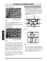
Fig. 8.30
•
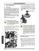
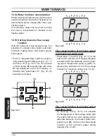
Enter the ”programming mode” by se
-
quentially pressing and holding in keys,
16 - 17
and then
18 (Fig. 8.31) for 10
sec-
onds until the letters
Pr
that alternate
with
code
01
are displayed on the LCD
display,
indicating that ”parameter
01”
(Fig. 8.32)
has been activated.
Fig. 8.31
14
15
16
17
18
19
Fig. 8.32
•
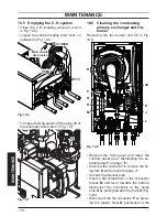
Press keys 16 and 18 (Fig. 8.31) at the
same
time until the value of parameter 01
(
65=
ADVANCE 25C
or 68=
ADVANCE
30C
or 66=
ADVANCE 35C
)
is displayed
on the LCD display (Fig. 8.33).
Summary of Contents for ADVANCE 25C
Page 87: ......


