


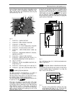


Gas valve
22
flue
exhaust
sampling point
air intake
sampling point
Fig. 8.4
12
Turn on the boiler, switching on the fused spur
isolation switch.
13
Open the gas inlet valve.
14
Turn on the boiler and operate for 2 minuets to
pre---heat the flue, before commencing any ad-
justments
A
B
C
Fig. 8.5
15
To enter in the parameters setting mode press
contemporary the 3 keys (
A
---
B
---
C
Fig. 8.5) for
10 second until the display shows Fig. 8.6
Fig. 8.6
Adjusting minimum gas valve setting
16
Press keys A and C (Fig. 8.5) at the same time
until the display shows the letters
LP
that alter-
nate with the heating water temperature value
(e.g.
45
), indicating the activation of the ”chimney
sweep function” at minimum output (Fig. 8.7).
Fig. 8.7
17
Make sure that the room thermostat is in the “heat
request” position.
18
Allow the analyser to give a stable reading.
19
Read the CO
2
% value.
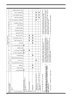
It should be between:
Model
Type gas
CO
2
% value
(range)
Activ A 12OV
A ti A 15OV
Natural (G20)
8,2 --- 9,0
Activ A 15OV
Propane (G31)
9,2 --- 10,2
Activ A 20OV
A ti A 25OV
Natural (G20)
8,2 --- 9,2
Activ A 25OV
Propane (G31)
9,2 --- 10,2
Tab. 8.1
To adjust the CO
2
% value remove the brass plug by un-
screwing it and rotate the Allen key screw ø 4 mm (2 ---
Fig. 8.2) (by rotating it clockwise the CO
2
% increases).
Checking the maximum gas valve setting
20
Press key A to vary the output in chimney sweep
mode: when the display shows the letters
cP
that
alternate with the heating water temperature
value (e.g.
60
), the ”chimney sweep function” is at
maximum output in heating mode (Fig. 8.8);
Fig. 8.8
21
Press further key A. The display shows the letters
dP
that alternate with the heating water tempera-
ture value (e.g.
60
)(Fig. 8.9). On this models this
step is not relevant and the value shown is the
same of the step 20. No setting is needed on this
step.