


Condensing heat exchanger
11
17
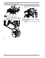
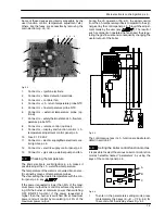
Loosen the connection
Q
and remove the pipe
R
(Fig. 5.4) from the Condensing heat exchanger.
18
Unscrew the screws
S
.
19
Remove the fan---burner group.
V
W
D
M
Q
R
X
Fig. 5.4
20
Unscrew the screws
T
and remove the plate
U
(Fig. 5.5).
21
Remove the forks
V
and remove the condensate
trap
W
moving it downwards (Fig. 5.4).
T
U
Fig. 5.5
22
Loosen the screws
X
(Fig. 5.4 --- Fig. 5.2)
23
Unscrew the screws
Y
(Fig. 5.2).
24
Remove the Condensing heat exchanger slightly
move it upwards, turn it frontwards freeing it from
the below screws
X
(Fig. 5.4 --- Fig. 5.2) and then
extract it forwards.
25
Reassemble the Condensing heat exchanger
carrying out the removal operations in reverse
order.
Ensure to tighten the screws
S ---
Fig. 5.2 firmly
5.3
Cleaning
If there are deposits of dirt between the fins of the Con-
densing heat exchanger, clean with a bristle paintbrush
and remove the dust with a hoover.
Warning: After cleaning or replacement as
detailed above, it is deemed necessary to
undertake a combustion analysis as detailed
in chapter 8.3 section 11.