


21
8
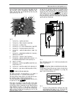
Gas valve
8.1
Function
The Gas valve
A
in Fig. 8.1 controls the gas inflow to the
boiler burner.
A
Fig. 8.1
By means of an electric command given to the on---off
operators the passage of the gas through the Gas valve
can be opened or closed.
8.2
Description of the parts (Fig. 8.2)
3
4
2
5
1
Fig. 8.2
1
Maximum gas pressure adjustment
2
Minimum gas pressure adjustment
3
On---off operators
4
On---off operators electric connector
5
Gas valve inlet pressure test point
8.3
Adjustment
Warning: isolate the boiler from the mains
electricity supply before removing any
covering or component.
Check the supply pressure before making any ad-
justment to the gas valve.
1
Close the gas inlet valve.
2
Remove the front panel of the case and lower the
control panel (see sections 2.2 and 2.3).
3
Loosen the internal screw on the Inlet Pressure
Test Point 5 (Fig. 8.2) of the Gas valve and con-
nect a pressure gauge using a suitable hose.
4
Open the gas inlet valve.
5
Turn on the electricity supply to the boiler, switch-
ing on the fused spur isolation switch.
6
Set the boiler in c.h. function as illustrated in
Fig. 8.3
C.h.
function
Fig. 8.3
7
Make sure that the room thermostat is in the “heat
request” position.
8
Read the inlet pressure value and ensure that it is
within the limits given in the table
Gas supply
pressures,
of the user/installation manual
If it does not comply with the required pressure
check the gas supply line and governor for faults
and/or correct adjustment.
9
Switch off the boiler
close the gas inlet valve.
10
Disconnect the pressure gauge and close the
Inlet Pressure Test Point 5 (Fig. 8.2).
Gas valve adjustment
The person carrying out a combustion
measurement should have been assessed as
competent in the use of a flue gas analyser
and the interpretation of the results.
The flue gas analyser used should be one
meeting the requirements of BS7927 or
BS--EN50379--3 and be calibrated in
accordance with the analyser manufacturers’
requirements, and have a current calibration
certificate.
11
Fit the probe of the flue analyser in the flue ex-
haust sampling point located on the exhaust
pipes of the boiler (Fig. 8.4).