


18
7
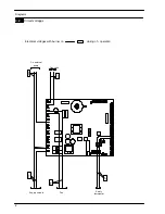
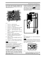
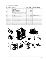
Control panel electronic p.c.b.
7.1
Function
A
C
B
D
Fig. 7.1
A
) C.h. temperature increase key
B
) C.h. temperature reduce key
C
) Reset/Stand---by/Winter/Summer key
D
) Display
The
Control panel electronic p.c.b.
can give to the ser-
vice 3 levels of informations:
f
Normally information
f
Info modality
f
Function modes setting modality
7.2
Normaly information
KEY
RESET
The symbol indicates that the boiler
can be directly reactivated by the user,
by pressing the reset button.
The symbol indicates that the fault re-
quires intervention on behalf of specia-
lised technical assistance.
All symbols represented with lines that
surround them, indicate that the sym-
bol is flashing.
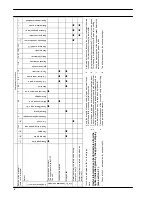
SIGNAL DISPLAYED BY THE LCD
LCD
FUNCTION
Er 01
+ RESET Lack of burner ignition on safety
lockout
Er 02
+ RESET Safety thermostat intervention
lockout
Er 03
+ RESET General lockout
Er 10
+ RESET Flue probe interven lockout
Er 14
+ RESET Faulty pump or primary tempera-
ture above 105
˚
C
Er 15
+ RESET
None or too low water flow; Faulty
pump (temp. difference between
probes higher than 35
˚
C)
Er 16
+ RESET
Possible exchange of NTC probes
(Flow or Return) or pump wrongly
mounted (upside --- down)
LCD
FUNCTION
Er 17
+ RESET Faulty c.h. temp. probe NTC
(Flow or Return)
Er 18
+ RESET Faulty primary circuit (no water or
absence of flow)
Er 04
+
Faulty primary circuit (no water or
absence of flow)
Er 05
+
Faulty fan control system
Er 06
+
Faulty c.h. temp. probe NTC
Er 08
+
Faulty external temp. probe NTC
Er 09
+
Faulty flue temp. probe NTC
Boiler Stand---By (anti---freeze
protection activaded)
Boiler waiting for heat request.
Boiler in winter mode.
The primary circuit temperature is
displayed.
Boiler on demand for c.h. power.
Burner ignition (spark)
Flame present (Burner on)
Boiler in anti---freeze phase (bP
fla temperature flashing)
Boiler in antifrost phase (AF
fla temperature flashing)
Set c.h.
(all other symbols are disabled)
Pump activated for the post---cir-
culation phase (Po fl
temperature flashing)