


- 55 -
INST
ALLA
TION
COMMISSIONING
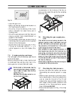
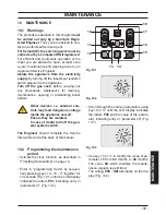
Fig. 7.6
•
Open the gas cock
•
Make sure that the ambient thermostat is in
the “heat request” position”.
•
Check the correct functioning of the boiler
both in domestic hot water mode and in
heating mode.
•
Check the gas pressures and flow rates as
shown in section "GAS CONVERSION" on
page 67 of this booklet.
•
Check that the condensate produced during
functioning fills the syphon
and is regularly
drained in the
draining pipe
.
•
Switch off the boiler by pressing the 13 (Fig.
7.5) key for 2 seconds until the
symbol appears on the LCD display (Fig.
7.4).
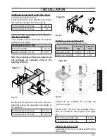
7.5 Condensate pipe and traps
The full length of the condensate pipe should
be check for leaks.
Before running the boiler, ensure that the built
in condensate trap and any other trap in the
drain system is correctly filled with water.
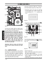
Fill the built in condensate trap by
removing the flue elbow and pour
-
ing a cupful of water into the flue
outlet (Fig. 7.7).
Warning do not allow water to en-
ter the outer air intake.
Fig. 7.7
An alternative, to the removal of the flue el
-
bow, pour the water through the flue sampling
point (Fig. 7.8).
Fig. 7.8
Sampling points
Flue exhaust
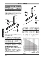
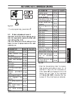
7.6 Checking the gas supply pres-
sure
This boiler has been factory tested to the
highest quality control standards and set
for the minimum and maximum gas work
-
ing pressures, connected to a 1 m flue and
a gas supply pressure of 20 mbar.
Any variation in gas supply pressure or
flue length may result in the customer ex
-
periencing a harmonic noise from the boil-
er. In these circumstances, it may be nec-
essary to reset the burner gas pressures
in accordance with section 11 Gas Valve of
the Service Manual.
It should be noted that a Flue Gas Analyser
is required for this procedure.
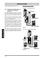
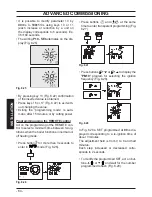
7.7 Checking the inlet pressure
•
Remove the boiler front panel, see
section
"Dismantling the external panels" on page
70.
•
With the boiler switched on at full rate (maxi
-
mum output power), check the supply pres
-
sure by using the 32 point in Fig. 7.9
and
compare the value with that reported on the
Gas supply pressure table (minimum inlet
pressure) in the "Technical Data" section
(pag. 28
Inovia 25S ERP
.
•
Ensure the test nipple 32 in Fig. 7.9 is firmly
closed.


