


- 40 -
INST
ALLA
TION
INSTALLATION
Fig. 6.4
9
7
6.7
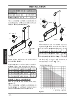
Fitting the flue system
For a correct installation of the flue pipe, refer
to the sheet provided together with the pre-
selected kit.
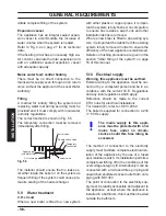
The horizontal run
of the flue pipes must in
-
cline about 1.5 degrees (25 mm per meter);
therefore the terminal must be higher than the
intake at the boiler.
The standard horizontal flue kit must be fitted
horizontal as the
inner flue exhaust pipe
is al-
ready angled with the correct incline.
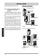
CORRECT system for installing the wall
flue
Fig. 6.5
A+S
ASA
A
= air intake
S
= flue exhaust
6.8
Choice of flue
The flue exhaust/air intake can be
installed in
the mode:
C
13
C
33
C
53
C
63
The terminal must be higher than
the boiler.
T
he following kits to be connected to the boiler
are available:
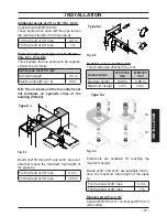
Wall flue exhaust kit (Fig. 6.6 A)
This kit allows the flues to be exhausted in the
rear wall or at the side of the boiler.
Coaxial pipe Ø 60/100 (A)
Nominal length
0.915 m
Minimum length
0.5 m
Maximum length
10 m
Fig. 6.6
B
A
C
45°
90°
Type C
13
Vertical flue exhaust kit with 90° bend (Fig.
6.6 B)
This kit allows the boiler exhaust axis to be
lifted by 635 mm.
The terminal must always exhaust horizon
-
tally.
Coaxial pipe Ø 60/100 with 90° bend (B)
Nominal length
1.55 m
Minimum length
0.5 m
Maximum length
10 m


