


14) SAFETY DEVICES
Note: only use receiving safety devices with free changeover contact.
14.1) TESTED DEVICES Fig. O
14.2) CONNECTION OF 1 PAIR OF NON-TESTED PHOTOCELLS FIG. H
15) CALLING UP MENUS: FIG. 1
15.1) PARAMETERS MENU (
PARA
) (PARAMETERS TABLE “A”)
15.2) LOGIC MENU (
LOGIC
)
(LOGIC TABLE “B”)
15.3) DEFAULT MENU (
default
)
Restores the controller’s DEFAULT factory settings.
15.4) LANGUAGE MENU (
language
)
Used to set the programmer’s language on the display.
15.5) STATISTICS MENU (
STAT
)
Used to view the version of the board, the total number of operations (in hundreds), the
number of transmitters memorized and the last 30 errors (the first 2 digits indicate the
position, the last 2 give the error code). Error 01 is the most recent.
15.6) PASSWORD MENU (
PASSWORD
)
Used to set a password for the board’s wireless programming via the U-link network.
With “PROTECTION LEVEL” logic set to 1,2,3,4, the password is required to access the
programming menus. After 10 consecutive failed attempts to log in, you will need to wait 3
minutes before trying again. During this time, whenever an attempt is made to log in, the
display will read “BLOC”. The default password is 1234.
16) OPENING DIRECTION REVERSAL (FIG. N1)
If the “op.dir.rev.” logic is on 1 the opening direction is reversed in comparison with the
standard operation and the limit switches are interpreted the opposite way.
17) CONNECTION WITH EXPANSION BOARDS AND UNIVERSAL HANDHELD PROGRAMMER
VERSION> V1.40 (Fig. B)
Refer to specific manual.
18) RADIO-RECEIVER (Fig. I)
The board comes ready for connection of removable radio-receiver.
The receiver’s channel 1 controls input IC1.
The receiver’s channel 2 controls terminals 26-27.
19) U-LINK OPTIONAL MODULES
Refer to the U-link instructions for the modules.
The use of some models causes lowered radio capacity. Adjust the system using an appropriate
antenna tuned to 433MHxz.
20) OPPOSING SLIDING DOORS (FIG.R)
REFER TO THE INSTRUCTIONS FOR THE U-LINK MODULES
WARNING: In the opposite leaves configuration, the SAFE 2 of the MASTER must be set as edge.
The configuration of the SAFE 2 safety logic, set in the Master control unit, is valid also for the
Slave control unit.
21) RESTORING FACTORY SETTINGS (Fig.S)
WARNING:
this operation will restore the control unit’s factory settings and all transmitters
stored in its memory will be deleted.
WARNING! Incorrect settings can result in damage to property and injury to people and animals.
- Cut off power to the board (Fig.S ref.1)
- Open the Stop input and press the - and OK keys together (Fig.S ref.2)
- Switch on the board’s power (Fig.S ref.3)
- The display will read RST; confirm within 3 sec. by pressing the OK key (Fig.S ref.4)
- Wait for the procedure to finish (Fig.S ref.5)
- Procedure finished (Fig.S ref.6)
22) WIRING DIAGRAM OF THE ONBOARD CONTROLLER FIG. P-Q
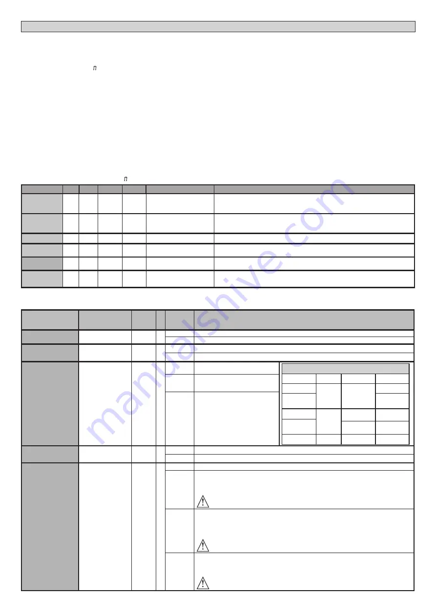
TABLE “A” - PARAMETERS MENU - (
PARA
)
Parameter
min.
max.
Default
Personal
Definition
Description
OPEN WORK.T
10
300
300
Opening operation time [s]
Maximum motor operation time, during opening.
Set the operation time so that it’s slightly longer than the complete operating cycle time.
CLS WORK.T
10
300
300
Closing operation time [s]
Maximum motor operation time, during closing.
Set the operation time so that it’s slightly longer than the complete operating cycle time.
TCA
0
180
40
Automatic closing time [s]
Waiting time before automatic closing.
TRF.LGHT.
CLR.T
1
180
40
Time-to-clear traffic light
zone [s]
Time-to-clear for the zone run through by traffic controlled by the traffic light.
PARTIAL
OPENING
3
300
5
Partial opening time[%]
Partial opening time following the activation of the PED pedestrian control. It must be less
than the opening work time.
Maintenance
0
250
0
Programming number of
operations for maintenance
threshold [in hundreds]
Allows you to set a number of operations after which the need for maintenance will be reported
on the AUX output configured as Maintenance or Flashing Light and Maintenance .
(*) In the European Union, apply standard EN 12453 for force limitations, and standard EN 12445 for measuring method.
TABLE “B” - LOGIC MENU - (
LOGIC
)
Logic
Definition
Default
Cross
out
setting
used
Optional extras
TCA
Automatic Closing
Time
0
0
Logic not enabled
1
Switches automatic closing on
FAST CLS.
Fast closing
0
0
Logic not enabled
1
Closes 3 seconds after the photocells are cleared before waiting for the set TCA to elapse.
STEP-BY-STEP
MOVEMNT
Step-by-step
movement
0
0
Inputs configured as Start E, Start I,
Ped operate with 4-step logic.
step-by-step mov.
2 STEP
3 STEP
4 STEP
CLOSED
OPENS
OPENS
OPENS
DURING
CLOSING
STOPS
OPEN
CLOSES
CLOSES
CLOSES
DURING
OPENING
STOP + TCA
STOP + TCA
AFTER STOP
OPENS
OPENS
OPENS
1
Inputs configured as Start E, Start I,
Ped operate with 3-step logic. Pulse
during closing reverses movement.
2
Inputs configured as Start E, Start I,
Ped operate with 2-step logic. Move-
ment reverses with each pulse.
PRE-ALARM
Pre-alarm
0
0
The flashing light comes on at the same time as the motor(s) start.
1
The flashing light comes on approx. 3 seconds before the motor(s) start.
HOLD-TO-RUN
Deadman
0
0
Pulse operation.
1
Deadman mode.
Input 64 is configured as OPEN UP.
Input 65 is configured as CLOSE UP.
Operation continues as long as the OPEN UP or CLOSE UP keys are held down.
WARNING: safety devices are not enabled.
2
Emergency Deadman mode. Usually pulse operation.
If the board fails the safety device tests (photocell or safety edge, Er0x) 3 times in a row, Deadman
mode is enabled which will stay active for 1 minute after the OPEN UP - CLOSE UP keys are released.
Input 64 is configured as OPEN UP.
Input 65 is configured as CLOSE UP.
WARNING: with the device set to Emergency Deadman mode, safety devices are not enabled.
3
Pulse operation during opening.
Deadman mode during closing.
Input 64 is configured as PULSE OPEN.
Input 65 is configured as CLOSE UP.
WARNING: safety devices are not enabled during closing.
D812213 00100_08
24 -
SP 3500 - SP 3500 SF
INSTALLATION MANUAL


