background image

INSTALLATION MANUAL

9.5) MENU LINGUA (

lingua

)

Used to set the programmer’s language on the display.  

9.6) MENU AUTOSET (

AUTOset

)  FIG.V


•  Launch an autoset operation by going to the relevant menu.

•  As soon as you press the OK button, the “.... ....  ....” message is displayed and the control 

unit commands the device to perform a full cycle (opening followed by closing), dur-

ing which the minimum torque value required to move the leaf is set automatically.

  During this stage, it is important to avoid breaking the photocells’ beams and not 

to use the START and STOP commands or the display.

  Once this operation is complete, the control unit will have automatically set the 

optimum torque values. Check them and, where necessary, edit them as described 

in the programming section.

WARNING!! Check that the force of impact measured at the points 

provided for by standard EN 12445 is lower than the value laid down 

by standard EN 12453.

Warning!! While the autoset function is running, the obstacle detection 

function is not active. Consequently, the installer must monitor the 

automated system’s movements and keep people and property out of range 

of the automated system.

9.7) MENU REGOLAZIONE FINECORSA FIG. U

The VENERE D control panel has an opening and closing limit switch adjustment 

menu, which simplifies the installation procedure.

Proceed as follows:  

•  Launch a limit switch adjustment operation by going to the relevant menu 

on the VENERE D panel (Fig.B).

•  When the “CLOSE” message is displayed, move the door to the desired closed 

position using the “UP” and “DOWN” buttons on the control unit, bearing in 

mind that the “DOWN” button closes the door, while the “UP” button opens 

the door. As soon as the door is in the desired closed position, press the “OK” 

button to store the closed travel limit position.

•  When the “OPEN” message is displayed, move the door to the desired open 

position using the “UP” and “DOWN” buttons on the control unit, bearing in 

mind that the “DOWN” button closes the door, while the “UP” button opens 

the door. 

  As soon as the door is in the desired open position, press the “OK” button to 

store the open travel limit position.

•  Position the “runner stop” correctly up against the runner and secure in place 

with the screws (fig.U rif.6 A-B).

  NOTE: These operations must be performed in “deadman” mode at reduced 

speed and without the safety devices operating.

9.8) STATISTICS

Connect the UNIVERSAL HANDHELD programmer to the control unit, enter the 

CONTROL UNIT/STATISTICS menu and run through the statistics parameters screen:

-  Software version of card microprocessor.

-   Number of cycles performed. If the motors are replaced, write down the 

number of operations performed so far.  

-  Number of cycles performed since last service. Automatically reset every time 

self-diagnosis is run or parameters are written.

-  Date of last service. Must be updated manually via the relevant “Update service 

date” menu

-  System description. Allows for 16 characters to be entered to identify the 

system.

10) REMOTE TRANSMITTER PROGRAMMING  FIG. X

This mode does not require access to the control panel.

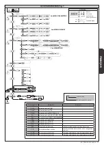
11) SERIAL CONNECTION VIA SCS1 CARD (Fig.Y)

The VENERE D control panel’s special serial inputs and outputs (SCS1) make the 

centralized connection of a number of automated devices possible. That way, all the 

automated devices connected can be opened or closed with a single command.

Connect all VENERE D control panels using twisted pair cabling only, proceeding 

as shown in the diagram in Fig. Y. 

When using a telephone cable with more than one pair, it is essential to use wires 

from the same pair.

The length of the telephone cable between one unit and the next must not 

be greater than 250 m.

At this point, each VENERE D control panel needs to be configured appropriately, 

starting by entering a MASTER control panel that will have control over all the 

others, which therefore have to be set as SLAVE units (see logic menu).

Also set the Zone number (see parameters menu) in the range 0 to 127. 

The zone number allows you to create groups of automated devices, each of 

which answers to the Zone Master. Each zone can have only one Master: the 

Master of zone 0 also controls the Slaves of the other zones.  

12) FUSE REPLACEMENT FIG. Z

13) ACCESSORIES FIG. Z1

SM1    External release device to be applied to the cremone bolt already fitted 

to the overhead door (1).

SET/S    External release device with retracting handle for sectional doors mea-

suring max 50mm (2).

ST   

  Automatic bolt release device for spring-operated overhead doors. Fitted 

to the control arm, it automatically releases the side door bolts (3).

TABLE “A” - PARAMETERS MENU - (

PARA

)

Parameter

min.

max.

Default

Personal

Definition

Description

TCA

180

40


Automatic

Closing Time [s] Set the numerical value of the automatic opening time in the range 1 to 180 seconds.


Op.Torque

 1

99

50


Opening torque 

[%]  

Set the numerical value of the motor’s opening torque in the range 1% to 99%.

WARNING: Check that the force of impact measured at the points provided for 

by standard EN 12445 is lower than the value laid down by standard EN 12453.

Setting sensitivity incorrectly can result in damage to property and injury to 

people and animals.

Cls.Torque

 1

99

50


Closing torque 

[%]  

Set the numerical value of the motor’s closing torque in the range 1% to 99%.

WARNING: Check that the force of impact measured at the points provided for 

by standard EN 12445 is lower than the value laid down by standard EN 12453.

Setting sensitivity incorrectly can result in damage to property and injury to 

people and animals.

part.open

000.1 006.0

001.0

Partial opening 

[m]

Set the numerical value of partial opening in the range 10 cm (0.001) to 6 m (006.0)

zona

0

127

0

Zona

Set the zone number between a minimum value of 0 and a maximum value of 127. 

See section 11 entitled “Serial connection”.

op speed

70

99

99

Running speed 

during opening  

[%]

Sets the maximum opening speed reached by the actuator at running speed. 

 The value is given as a percentage of the maximum speed the actuator can reach.

cl speed

70

99

99

Running speed 

during closing 

[%]  

Sets the maximum closing speed reached by the actuator at running speed. 

The value is given as a percentage of the maximum speed the actuator can reach.

dist.sloud

7

100

7

Slow-down 

distance [cm]

Sets the slow-down distance travelled by the actuator during opening and clos-

ing. 

Editing one of the following parameters:

-  Running speed during opening

-  Running speed during closing

-  Slow-down distance

results in the actuator performing a complete opening/closing cycle with the anti-crush feature switched off. The “SET” message flashes on the display to warn that 

this cycle is in progress.

ENGLISH

BOTTICELLI B CRC 480 D01 - 

15

D811882 00100_03

Summary of Contents for BOTTICELLI B CRC 480 D01

Page 1: ...MATION POUR PORTES BASCULANTES ET SECTIONALES GARAGENTORANTRIEB FÜR SCHWING UND SEKTIONALTORE AUTOMATIZACIONES PARA PUERTAS BASCULANTE Y SECCIONALES AUTOMATISERINGEN VOOR KANTEL EN SECTIEDEUREN Attenzione Leggere attentamente le Avvertenze all interno Caution Read Warnings inside carefully Attention Veuillez lire attentivement les Avertissements qui se trouvent à l intérieur Achtung Bitte lesen Si...

Page 2: ...issaggio Fastening configuration Configuration de la fixation Konfigurierung Befestigung Configuración de fijación Configuratie van bevestiging 1 DFBBFD 2 DCFFCD 3 DCGGCD 4 FBBF 5 EAAE 6 EBBE 7 GBBG A A D B E E F F G B D C C 7x0 5 mm 2 LINEA 3x1 5 mm2 2x0 5 mm 2 5x0 5 mm 2 INSTALLAZIONE VELOCE QUICK INSTALLATION INSTALLATION RAPIDE SCHNELLINSTALLATION INSTALACIÓN RÁPIDA SNELLE INSTALLATIE 2 BOTTIC...

Page 3: ...J 1 2 3 4 C1 P1 5 L1 L2 C C D D B A D Tassello Plug Cheville Dübel Taco Plug Ø 10 V1 V2 V1 4 8 V2 16 4 8 V4 V5 V6 V6 R1 R1 R2 D1 D1 D2 R2 8 4 8 4 8 6 16 8 6 3 8 60 60 V5 D1 V6 D2 V4 V3 6 20 V3 V3 V5 R1 R2 R1 R2 R2 V5 BOTTICELLI B CRC 480 D01 3 D811882 00100_03 ...

Page 4: ...e échelle 1 1 Schneidschablone Maßstab 1 1 Plantilla para corte escala 1 1 Kaliber voor snijden schaal 1 1 88 1 2 3 4 5 2 4 1 3 E14 24V 25W max 253 16 65 378 35 3380 2780 3760 3160 250 146 17 V1 V1 V2 4 8 4 8 16 8 4 V1 4 8 V1 V1 8 30 V1 V2 4 BOTTICELLI B CRC 480 D01 D811882 00100_03 ...

Page 5: ...ampe de courtoisie Hilfsbeleuchtung Luz interior waaklicht Fusibile Fuse Fusible Schmelzsicherung Fusible Zekering COM PED 16 17 JP10 JP2 Connettore scheda opzionale Optional board connector Connecteur carte facultative Steckverbinder Zusatzkarte Conector de la tarjeta opcional Connector optionele kaart Display tasti programmazione Display programming keys Afficheur touches programmation Display P...

Page 6: ... già memorizzato Radio transmitter already memorised Radiocommande déjà mémorisée Bereits gespeicherte Funksteuerung Radiomando ya memorizado Reeds gememoriseerde afstandsbediening Radiocomando da memorizzare Radio transmitter to memorise Radiocommande à mémoriser Zu speichernde Funksteuerung Radiomando que memorizar Te memoriseren afstandsbediening Radiocomando da memorizzare Radio transmitter to...

Page 7: ...esso FINECORSA CHIUSURA ped Attivazione ingresso PEDONALE open Attivazione ingresso OPEN CLS Attivazione ingresso CLOSE amp Inversione per ostacolo Verificareeventualiostacolilungo il percorso ER01 Test fotocellule fallito Verificare collegamento foto cellule e o impostazioni logiche ER10 Errore test hardware scheda Rivelati problemi al circuito di comando motore ER11 Errore test hardware scheda R...

Page 8: ...nte in posizione visibile fissare inoltre alla struttura un cartello di Attenzione Fissareinmodopermanenteunaetichettarelativaalfunzionamentodellosblocco manuale dell automazione e apporla vicino all organo di manovra Assicurarsi che durante la manovra siano evitati o protetti i rischi meccanici ed inparticolarel impatto loschiacciamento ilconvogliamento ilcesoiamentotra parte guidata e parti circ...

Page 9: ...ta binario senza fissarle al telaio della porta Fig L1 o se l al tezza lo consente montare la staffa fissandola all architrave in muratura con tasselli Fig L2 7 Alzare la testa motorizzata fino ad appoggiare il tutto al soffitto e inserirvi le viti di fissaggio che bloccano il binario comprese le viti della staffa di ancoraggio 8 Nel caso in cui il fissaggio della testa motore e del binario non fo...

Page 10: ... di un menu di regolazione dei finecorsa di apertura e chiusura che semplifica la procedura di installazione Procedere come segue Dareavvioadunaoperazionediregolazionefinecorsaportandosinell apposito menu del quadro VENERE D Fig A Alla visualizzazione del messaggio CLOSE portare l anta nella posizione di chiusuradesideratautilizzandoipulsanti UP e DOWN dellacentrale tenendo presente che il pulsant...

Page 11: ...azione radiocomandi ON ON Abilita la memorizzazione via radio dei trasmettitori 1 Premere in sequenza il tasto nascosto P1 e il tasto normale T1 T2 T3 T4 di un trasmettitore già memorizzato in modalità standard attraverso il menu radio 2 Premere entro 10s il tasto nascosto P1 ed il tasto normale T1 T2 T3 T4 di un trasmettitore da memorizzare La ricevente esce dalla modalità programmazione dopo 10s...

Page 12: ... activated STOP STOP input activated PHOT PHOT input activated SWO OPENING LIMIT SWITCH input activated SWc CLOSING LIMIT SWITCH input activated ped PEDESTRIAN input activated open OPEN input activated CLS CLOSE input activated AMP Reverse due to obstacle Check for obstacles in path ER01 Photocell test failed Check photocell connection and or logic settings ER10 Board hardware test error Problems ...

Page 13: ...e public Apply at least one warning light flashing light in a visible position and also attach a Warning sign to the structure Attach a label near the operating device in a permanent fashion with informa tion on how to operate the automated system s manual release Make sure that during operation mechanical risks are avoided or relevant protective measures taken and more specifically that nothing c...

Page 14: ...he help of an adequate support lift the entire motor screw the screws onto the track holding bracket without fixing them to the door frame Fig L1 or if the height allows it fit the bracket to the masonry lintel by means of plugs Fig L2 7 Rest the motor onto the floor taking care not to damage it and fix the articulated bracket to the door frame or to the ceiling 8 In the case where the motor is no...

Page 15: ...possible Thatway allthe automated devices connected can be opened or closed with a single command ConnectallVENEREDcontrolpanelsusingtwistedpaircablingonly proceeding as shown in the diagram in Fig Y When using a telephone cable with more than one pair it is essential to use wires from the same pair The length of the telephone cable between one unit and the next must not be greater than 250 m Atth...

Page 16: ...Remote control programming ON ON Enables wireless memorizing of transmitters 1 Press in sequence the hidden key P1 and normal key T1 T2 T3 T4 of a transmitter that has already been memorized in standard mode via the radio menu 2 Press within 10 sec the hidden key P1 and normal key T1 T2 T3 T4 of a transmitter to be memorized The receiver exits programming mode after 10 sec you can use this time to...

Page 17: ...ntrée STOP PHOT activation entrée PHOTOCELLULE SWO activation entrée FIN DE COURSE OPEN SWc activationentréeFINDECOURSEFERMETURE ped activation entrée PIÉTON open activation entrée OPEN CLS activation entrée CLOSE AMP Inversion pour obstacle Vérifier éventuels obstacles le long du parcours ER01 Essai photocellules échoué Vérifier connexion photocellules et ou configurations logiques ER10 Erreur es...

Page 18: ...s pièces détachées originales pour les opérations d entretien ou les réparations Le Fabricant décline toute responsabilité quant à la sécurité et au bon fonctionnement de l automatisation en cas d utilisation de composants d autres Fabricants Ne modifier d aucune façon les composants de l automatisation sans l autorisa tion expresse du Fabricant Informer l utilisateur de l installation sur les ris...

Page 19: ...stre les diffé rentes combinaisons permettant de fixer l étrier sur le portail basculant 4 Percer le plafond avec une pointe D 10 en respectant les références mar quées précédemment et insérer les chevilles Fig I 5 Bloque le rail à la base fig J réf 1 2 et fig K réf 3 4 5 6 En s aidant d un appui adapté lever tout le moteur visser les vis sur l étrier porte rail sans les visser au châssis de la po...

Page 20: ...ccéder au tableau de commande 11 CONNEXION SÉRIE À TRAVERS LA CARTE SCS1 Fig Y Le tableau de commande VENERE D permet de connecter en les centralisant plusieurs automatisations à travers les entrées et les sorties série prévues à cet effet SCS1 Cela permet d accomplir avec un même commande l ouverture ou la fermeture de toutes les automatisations connectées En vous aidant du schéma de la figure Y ...

Page 21: ...des radiocommandes ON ON Active la mémorisation via radio des émetteurs 1 Appuyez en séquence sur la touche cachée P1 et sur la touche normale T1 T2 T3 T4 d un émetteur déjà mémorisé en mode standard à travers le menu radio 2 Appuyez dans les 10 secondes sur la touche cachée P1 et sur la touche normale T1 T2 T3 T4 d unémetteuràmémoriser Lerécepteursortdumodeprogrammationaprès10secondes durant ce l...

Page 22: ...ktivierung Eingang STOP PHOT Aktivierung Eingang PHOT SWO Aktivierung Eingang ENDSCHALTER ÖFFNUNG SWc Aktivierung Eingang ENDSCHALTER SCHLIESSUNG ped Aktivierung Eingang FUSSGÄNGER open Aktivierung Eingang OPEN CLS Aktivierung Eingang CLOSE AMP Umkehrung wegen Hindernis Auf Hindernisse auf dem Weg überprüfen ER01 Test Fotozellen fehlgeschlagen Überprüfung Anschluss Fotozellen und oder Einstellunge...

Page 23: ...ingestellt worden ist und dass die Schutzsysteme den Betrieb ordnungsgemäß blockieren Verwenden Sie bei allen Wartungs und Reparaturarbeiten ausschließlich Originaler satzteile Die Firma haftet nicht für die Sicherheit und den ordnungsgemäßen Betrieb der Automatik falls Komponenten von anderen Herstellern verwendet werden Nehmen Sie keine Änderungen an den Komponenten der Automatik vor die von der...

Page 24: ...rif 1 2 e Abb K rif 3 4 5 6 Mit Hilfe einer geeigneten Auflage den gesamten Motor anheben die Schrauben am Schienentragbügel anschrauben und nicht am Türrahmen befestigen Abb L1 Alternativ kann wenn die Höhe dies zuläßt der Bügel mit Dübeln am Mauersturz montiert werden Abb L2 7 Den Motorkopf anheben bis alles zusammen an der Decke anliegt Dann die Befestigungsschrauben der Schiene einführen einge...

Page 25: ...Anschließen mehrerer Automatisierungen Auf diese Weise ist es möglich mit einer einzigen Steuerung die Öffnung oder dieSchließungallerangeschlossenenAutomatisierungenauszuführen Befolgen Sie beim Anschließen aller Bedientafeln VENERE D den Schaltplan von Abb Y und verwenden Sie dabei ausschließlichTelefonschleifen BeiVerwendung eines Telefonkabels mit mehreren Leiterpaaren müssen unbedingt die Drä...

Page 26: ...iert die Abspeicherung der Sender über Funk 1 DrückenSienacheinanderdieversteckteTaste P1 unddienormaleTaste T1 T2 T3 T4 eines bereits in der Standardmodalität mit dem Menü Funk abgespeicherten Senders 2 Drücken Sie innerhalb von 10 Sek Die versteckteTaste P1 und die normaleTaste T1 T2 T3 T4 eines abzuspeichernden Senders Der Empfänger verlässt die Programmiermodalität nach 10 Sekunden innerhalb d...

Page 27: ...entrada STOP PHOT activación entrada PHOT SWO activación entrada FINAL DE CARRERA DE APERTURA SWc activación entrada FINAL DE CARRERA DE CIERRE ped activación entrada PEATONAL open activación entrada OPEN CLS activación entrada CLOSE AMP Inversión por obstáculo Comprobar eventuales obstáculos a lo largo del recorrido ER01 Prueba fotocélulas fallida Comprobarconexiónfotocélulasy oconfiguracioneslóg...

Page 28: ...vamente piezas originales para todas las operaciones de manteni miento y reparación La Empresa no se responsabiliza de la seguridad y el buen funcionamiento de la automatización en caso que se utilicen componentes de otros fabricantes No realizar ninguna modificación a los componentes de la automatización si no se cuenta con autorización expresa por parte de la Empresa Instruir al usuario de la in...

Page 29: ...ciones para fijar la abrazadera al portón basculante 4 Perfore el techo con una broca D 10 respetando las referencias anterior mente marcadas e inserte los tacos Fisher Fig I 5 Bloqueelavíaalabase Fig J rif 1 2 e fig K rif 3 4 5 6 Con la ayuda de un apoyo adecuado levante todo el motor atornille los tor nillos a la abrazadera portavía sin fijarlos a la hoja de la puerta Fig L1 o si la altura lo pe...

Page 30: ...0 PROGRAMACIÓN DE LOS TRANSMISORES A DISTANCIA FIG X Este modo no requiere el acceso al cuadro de mando 11 CONEXIÓN SERIAL MEDIANTE TARJETA SCS1 Fig Y El cuadro de mando VENERE D permite mediante entradas específicas y salidas seriales SCS1 la conexión centralizada de varias automatizaciones De este modo se puede con un único mando realizar la apertura o el cierre de todas las automatizaciones con...

Page 31: ...code véase el apartado Clo nación de los Radiotransmisores prog radio Programación de los radiomandos ON ON Habilita la memorización vía radio de los transmisores 1 Pulsar en secuencia la tecla oculta P1 y la tecla normal T1 T2 T3 T4 de un transmisor ya memorizado en modo estándar a través del menú radio 2 Dentro de los 10 seg pulsar la tecla oculta P1 y la tecla normal T1 T2 T3 T4 de un transmiso...

Page 32: ...g START STOP activering ingang STOP PHOT activering ingang PHOT SWO activering ingang EINDAANSLAG OPENING SWc activering ingang EINDAANSLAG SLUITING ped activering ingang VOETGANGERS open activering ingang OPEN CLS activering ingang CLOSE amp Omkering voor obstakel Eventueleobstakelslangshettrajectcontroleren ER01 Test fotocellen mislukt Aansluiting fotocellen en of instelling logica s controleren...

Page 33: ...ren Uitsluitend originele reserveonderdelen gebruiken voor alle onderhouds of repara tiewerkzaamheden Het Bedrijf wijst iedere willekeurige verantwoordelijkheid af uit veiligheidsredenen en vanwege de goede werking van het automatiseringssysteem als er onderdelen van andere fabrikanten gebruikt worden Geen enkele wijziging uitvoeren aan de componenten van het automatiseringssys teem indien niet ui...

Page 34: ...ort te bevestigen 4 Het plafond doorboren met een punt D 10 en hierbij de referenties respec teren die eerder gemarkeerd werden en de pluggen invoeren Fig I 5 De rail aan de basis blokkeren fig J rif 1 2 en fig K rif 3 4 5 6 Met behulp van een adequate steun heel de motor optillen de schroeven op de beugel raildrager vastdraaien zonder deze vast te hechten aan het frame van de deur Fig L1 of indie...

Page 35: ...6 karakters van identificatie installatie in te voeren 10 PROGRAMMERING REMOTE TRANSMITTERS FIG X Deze modaliteit vereist niet de toegang naar het bedieningsbord 11 SERIËLE VERBINDING MIDDELS KAART SCS1 Fig Y HetbedieningsbordVENEREDstaat middelsdesbetreffendeseriëleingangenen uitgangen SCS1 degecentraliseerdeverbindingvanmeerdereautomatiseringen toe Op deze manier is het mogelijk met een enkele b...

Page 36: ...n ON ON Activeert de memorisering via radio van de transmitters 1 In sequens drukken op de verborgen toets P1 en de normale toets T1 T2 T3 T4 van een reeds gememoriseerde transmitter in de standaard modaliteit middels het menu radio 2 Binnen de 10s drukken op de verborgen toets P1 en de normale toets T1 T2 T3 T4 van een te memoriseren transmitter De ontvanger verlaat de modaliteit programmering na...

Page 37: ...lunque momento le modifiche che essa ritiene convenienti per migliorare tecnica mente costruttivamenteecommercialmenteilprodotto senzaimpegnarsiadaggiornare la presente pubblicazione USER WARNINGS GB WARNING Important safety instructions Carefully read and comply with the Warnings and Instructions that come with the product as improper use can cause injury to people and animals and damage to prope...

Page 38: ...ten Bewegungen der Tür führen Bei Rollladenautomatisierungen Überwachen Sie den Rollladen während der Bewegung und halten Sie Personen fern bis er vollständig geschlossen ist Gehen Sie bei der Betätigung der eventuellen Entsperrung mitVorsicht vor da der offene Rollladen bei Brüchen oder Abnutzung herunterfallen könnte Das Brechen oder die Abnutzung der mechanischen Organe der Tür geführter Teil w...

Page 39: ... hetbewegenderolluikcontrolerenendepersonenop eenafstandhoudentotdezenietvollediggeslotenis Oplettenwanneerdedeblokkeringwordt geactiveerd indien aanwezig omdat een open rolluik snel zou kunnen vallen in aanwezigheid van slijtage of gebreken Het stukgaan of de slijtage van mechanische onderdelen van de deur geleide deel zoals bijvoorbeeld kabels veren steunen klepscharnieren geleiders kan gevaren ...

Page 40: ...40 BOTTICELLI B CRC 480 D01 D811882 00100_03 ...

Reviews: