32
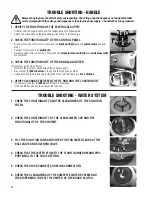
Remove the plug from the outlet before any inspection. The voltage and the frequency on the machine label
must correspond with the voltage and frequency of the electric power supply. The outlet has to be grounded.
1. VERIFY THE FUNCTIONS OF THE ELECTRICAL SUPPLY
• Confirm that the supply cable and the socket-plug are not damaged.
• Check the connection of the grounded power cable on the machine.
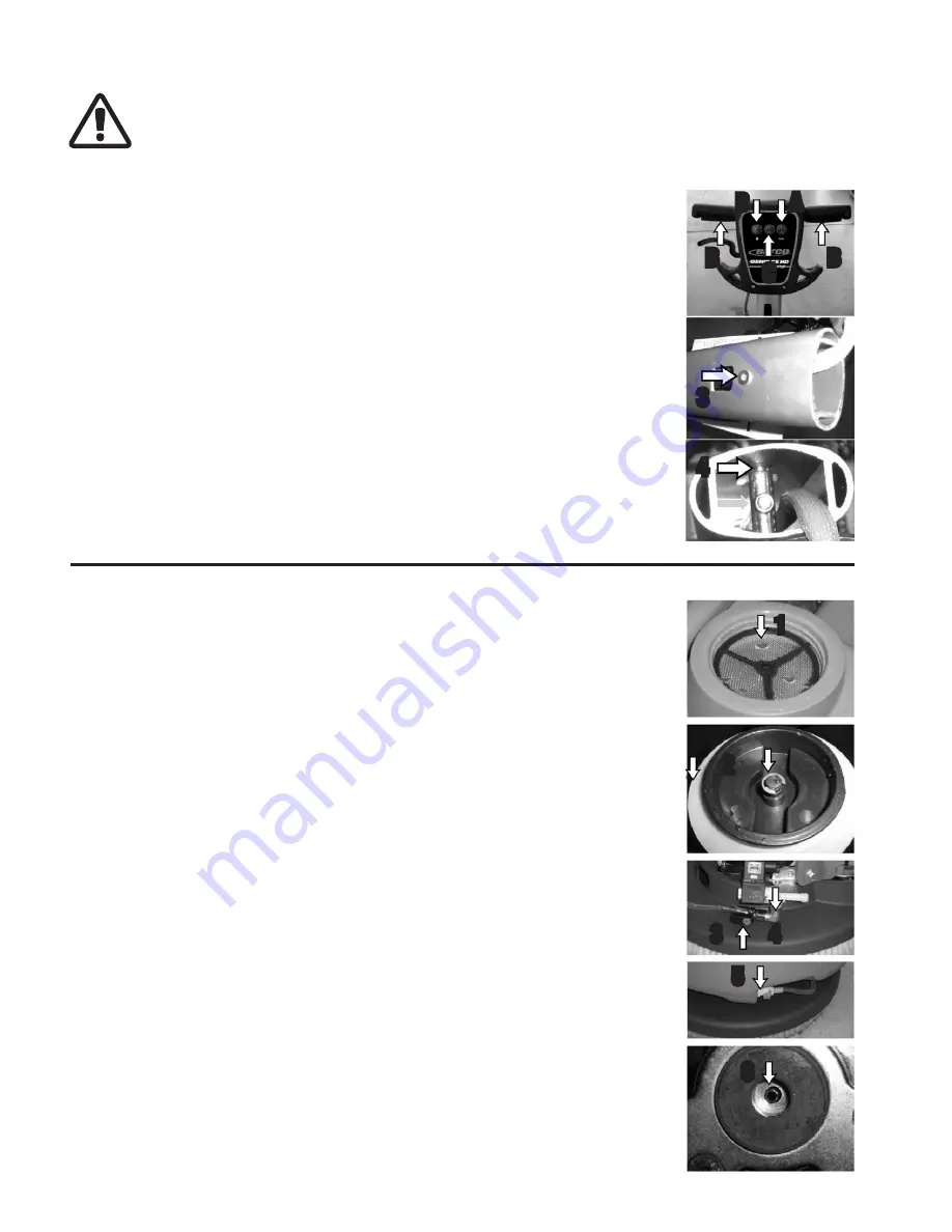
2. CHECK THE FUNCTIONALITY OF THE CONTROL PANEL
• Brush motor (the motor starts only when the
brush switch (A)
and the
switch levers
are actu-
ated).
• Vacuum motor (turn it on
switch (C)
).
• Solenoid valve (this is turned on only when the
solenoid valve switch (D)
and
switch levers (B)
are actuated).
3. CHECK THE FUNCTIONALITY OF THE HANDLE ADJUSTER
If necessary, adjust it as follow:
• Unscrew the 4 screws which attach the handle support.
• Be sure that the
M6x10 screw
is loose and that the pin can move.
• Check between the pin and the inside face of the rod that there are
2 to 3 threads
.
4. VERIFY CLEARANCE BETWEEN THE TIE ROD AND THE LOCKING BOLT
• If necessary unscrew the
M8 nut
until there is clearance.
• If the handle bar doesn’t lock, adjust the lock nut.
TROUBLE SHOOTING - HANDLE
1. CHECK THE FUNCTIONALITY AND THE CLEANLINESS OF THE SOLUTION
FILTER.
2. CHECK THE FUNCTIONALITY OF THE CLEAN WATER CAP AND THE
FUNCTIONALITY OF THE AIR VENT.
3. FILL THE SOLUTION TANK AND CHECK FOR FOR WATER LEAKS AT THE
BALL VALVE AND SOLENOID VALVE.
4. CHECK THAT THE WATER FLOW TO THE FLOOR IS UNIFORM AND PRO-
PORTIONAL TO THE VALVE SETTING.
5. CHECK THE QUICK CONNECT COUPLING CONNECTION.
6. CHECK THE CLEANLINESS OF THE COMPLETE WATER SYSTEM AND
THE DISPENSING TUBE AT THE CENTER OF THE BRUSH CLUTCH.
TROUBLE SHOOTING - WATER SYSTEM
1
2
3
4
5
6
A
3
4
B
C
B
D
Summary of Contents for GENIE CE HD APS
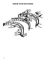
Page 18: ...18 SQUEEGEE SYSTEM PARTS DIAGRAM 6 3 4 13 14 12 11 5 18 1 7 10 8 8 18 15 16 5 9 5 17 2 9 ...
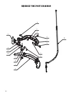
Page 20: ...20 SQUEEGEE YOKE PARTS DIAGRAM 4 2 11 13 10 6 7 5 2 6 7 9 14 12 8 3 1 ...
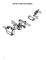
Page 28: ...28 ELECTRIC SYSTEM PARTS DIAGRAM 2 6 4 3 5 3 7 10 2 9 1 8 ...
Page 30: ...30 ELECTRICAL DIAGRAM ...
Page 31: ...31 ...

