


4
CHECKS AND MAINTENANCE
47
EN
2
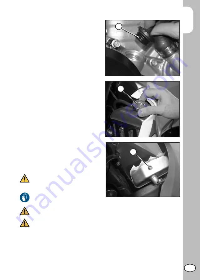
Close plug
2
.
WARNING:
Hot oil can cause severe burns!
ATTENTION:
Dispose of used oil in compliance with the
regulations in force.
Re-assemble the engine protection plate by
tightening the screws to 10Nm.
LIQUID COOLANT
CHECK THE LEVEL
Keep the vehicle in vertical position relative
to the ground.
The level of the coolant must be checked
when the engine is cold. Use the following
procedure:
- Unscrew cap
1
and ensure that the liquid
is visible in the lower portion of the load-
ing tube.
- In the case in which the liquid is not visible
remove the vent screw
2
and proceed
topping up.
- At the end of operation refit the filler cap
and the vent screw.
Use the oil indicated on page 13 in the
“Recommended lubricants and liquids” table.
WARNING: Never unscrew the
filler cap of the radiator when the
engine is hot. Danger of burning!
WARNING:
1
2
Wear appropriate protective clothing and protection gloves.
Keep coolant out of reach of children.
Avoid any direct contact of the coolant with skin, eyes or clothing. If this hap-
pens:
- with the eyes, rinse immediately with plenty of water and seek medical advice;
- with skin, Immediately clean contaminated areas with soap and water Change
clothing that is contaminated with coolant.
If coolant is swallowed, contact a doctor immediately.
Summary of Contents for RR 350 EFI 2018
Page 14: ...14 EN...


