background image

2 PC RESIN TOP COVER: 
Center small half over hole in the top plate as shown and
attach with a #12 screw. Slide the large half over the small
half and secure using two #10 screws.

ONE PIECE RESIN CLIP-ON COVER:

This installation requires no hardware. Simply hook the back end
of the top cover into place, and use your fingers or a screwdriver
to gently flex the front tabs enough to hook the cover in place.
Make sure that the top cover is centered over the upright when
installing.

Side view of top
cover and top rail

Swing this end around and 
gently flex tab into place.

*Bullnose rail is used for the illustration, 

but installation is the same for all 1 pc. 

clip-on resin covers.

Hook this
end first.

#12

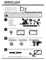
First, refer to box #16 on the reverse side of these instructions for the curved side top cover installation, follow-
ing the diagram that pertains to your pool.  If your pool has a 2 pc. resin top cover, refer to the diagrams below
for straight side top cover installation.
*On 6” top rail pools with 2 pc. top covers, the curved and straight side covers are the same.

STEP 18: STRAIGHT SIDE TOP COVER INSTALLATION:

#10

#2

*ONCE YOU HAVE COMPLETED THESE INSTRUCTIONS, REFER TO BOX #17 AT THE END OF THE ROUND INSTRUC-
TIONS (ON REVERSE SIDE) FOR FINAL INSTALLATION TIPS, POOL MAINTENANCE AND WINTERIZATION PROCE-
DURES, AS WELL AS ALL OTHER SAFETY INFORMATION PROVIDED.

STRAIGHT SIDE SUPPORT:
USED ON THE STRAIGHT
SIDE OF THE POOL -
NOTICE THE SQUARE
CUTOUT. USE ON OVAL
UPRIGHTS.

CURVED SIDE
ANGLE SUPPORT:
USE ON CURVED 
END UPRIGHTS.

TOP VIEW OF STRAIGHT
SIDE SUPPORT:
SMALLER PIECE THAT IS
OPEN IN BACK. USE ON
OVAL UPRIGHTS.

TOP VIEW OF CURVED
SIDE ANGLE SUPPORT:
LARGER THAN STRAIGHT
SIDE SUPPORT. HAS
BACK WALL. USE ON
CURVED END UPRIGHTS.

NO BACK WALL

TWO PIECE RESIN TOP COVER WITH ATTACHMENTS ON
THE SIDES:
There is a straight support with a square cutout to fit the oval
upright, instead of an angle support supplied for the curved
ends. It attaches the exact same way as the angle support.

LARGE TWO PIECE RESIN TOP COVER WITH ATTACHMENT
IN FRONT:
(DOES NOT INCLUDE 6” TOP RAIL POOLS.) The curved end
angle support is slightly larger than the straight support. The
straight support is not filled in the back.

BACK WALL

Summary of Contents for Belize

Page 1: ...cks to make pool inaccessible to toddlers and uninvited guests Make sure gate is always closed Be sure to follow local building code requirements for load capacity and fencing if using an aftermarket...

Page 2: ...to this level NOTE Area shown is slightly larger than actual pool area to help in installation POOL SIZE AREA NEEDED A to A A to B A to C FOR POOL 11 x 181 2 17 x 20 20 6 8 6 12 x 24 18 x 26 26 6 8 6...

Page 3: ...be outside of the pool Do so using four 20 x bolts and four 20 nuts in each STEP 2 PRE ASSEMBLY STEP 3 STRAP LAYOUT Unwind and straighten straps Bolt the strap end channels to each end of every strap...

Page 4: ...for the oval uprights that you have already installed Measure from outside of oval upright to outside of oval upright diagonally across as shown If the two measurements are equal the framework is squa...

Page 5: ...th screwdrivers at every other bottom rail to hold in place Install 2 x 8 x 16 patio blocks under each bottom plate making sure that patio blocks are absolutely level with the ground NOTE Check for le...

Page 6: ...out of the bottom plates and then double check the length of the straight sides If the ground is uneven the wall may jump out of the groove in the bottom rails Correct this condition if it happens X S...

Page 7: ...along the entire circumference We recommend that you start this in the middle of the straight sides and work your way towards the round sections This will help to push the wall firmly against the hold...

Page 8: ...ngs easier and more efficient down the line Now would be the time to install the fence brackets onto the uprights if you have a fence for the pool If you have not done so already install uprights on c...

Page 9: ...ATION Starting at the liner wall seam hang the liner over the wall making sure that the seam is straight up and down perpendicu lar to the floor This will assure you that your liner begins going over...

Page 10: ...NOT LEAVE A GAP BETWEEN LINER AND COVE THIS WILL CAUSE DOWNWARD PRESSURE ON THE LINER CORRECT THIS CONDITION IF IT OCCURS INNER STABILIZER RAIL LINER PLASTIC COPING ROLL LINER UP INWARD TO HIDE EXCESS...

Page 11: ...ion meets the straight side place the 28 5 16 top rails between the oval uprights and attach to oval top plates with 4 10 x screws two per side The longer top rails are for the curved sides which are...

Page 12: ...c top covers the curved and straight side covers are the same STEP 18 STRAIGHT SIDE TOP COVER INSTALLATION 10 2 ONCE YOU HAVE COMPLETED THESE INSTRUCTIONS REFER TO BOX 17 AT THE END OF THE ROUND INSTR...

Reviews: