


6
82.486 "AXIALE II" Booms
ADJUSTMENT OF THE ARMS
ADJUSTMENT OF THE BOOM
- Your boom is equipped with a device which adjusts arm alignment in working position and adjustment for
the transport position.
ADJUSTMENT OF THE MAIN ARMS
IN TRANSPORT POSITION
(figure 1)
:
Arms closed in transport position (they must be fully against the arm supports).
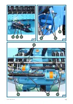
- Remove the pin (5) (figure 1) then actuate the unfolding actuators (1) in open position (end of travel).
- Adjustment of the ball joint (4):
- unscrew the set screw (2),
- unscrew the socket (3) to gain access to the set screw (6),
- adjust the ball joint (4) so that the pin (5) can be replaced easily,
- tighten the set screw (6) and adjust the socket (3) for working position.
IN WORK POSITION (IN THE HORIZONTAL PLANE):
Open the arms fully.
- Check the alignment in the horizontal plane.
- If not horizontal, decompress the actuators, then loosen the set screw (2) so that you can tighten or
loosen the socket (3) (figure 1).
- Open the arm again to check the alignment.
- Repeat the operation until the desired setting is obtained.
- Tighten the set screw (2).
IN WORK POSITION (IN THE VERTICAL PLANE):
Open the arms fully.
• Case of booms without GV (variable geometry)
(figure 2):
- Adjust the main arms (2) by turning the coupler (1) positioned on the upper part of the arm.
• Case of booms with GV (variable geometry)
(figure 4):
- These booms are equipped with a position indicator (2) and an optional automatic reset (2 position sensors
(1) (figure 3)). The actuator (1) (figure 4) is used to incline the arm.
• Adjustment of reset sensors
(figure 3):
- If your reset is not correct adjusted:
- open the arms in work position (see electrical control box, pages 17, 18 and 20),
- loosen the nuts (2),
- slide the sensors (1) into the opening up to the limit of illumination of the LED located on top of the
sensor; when the LED goes out, retighten the nuts of the sensor.
WARNING:
The sensors (1) (figure 3) must have a clearance (a) between 2 and 4 mm.
WARNING:
- Spray equipped with GV (variable geometry):
The GV must be positioned on 0 before folding the boom.
Summary of Contents for AXIALE II ED Series
Page 7: ...7 82 486 AXIALE II Booms 2 1 2 3 2 1 a 4 1 2 1 5 3 2 1 4 6 2 Detail of the ball joint...
Page 9: ...9 82 486 AXIALE II Booms 6 2 6 7 8 5 1 3 2 C 5 4 2 3 1 5...
Page 11: ...11 82 486 AXIALE II Booms 1 3 2 8 7 2 3 1 9 4 5 3 1 2 6 7...
Page 13: ...13 82 486 AXIALE II Booms 11 1 10 12 1 2 3 A 1 B 2 3...
Page 15: ...15 82 486 AXIALE II Booms 14 1 2 13 3 1 2 3 15 2 2 3 1 a...


