Berthoud AXIALE II ED Series Manual Download Page 17

   17

82.486  "AXIALE II" Booms

WHEN WORKING

- To modify the boom 

height

, use switch (3):

- raise it to lift the boom,
- push it down to lower the boom.

- If you want to fold an arm on the right or left, you must do the following:

- lock the boom by raising switch (2) and hold it,
- lift the boom, using switch (3),
- lower switch (9) or (10) and hold it until the right or left arm is completely closed.

- To modify the 

angle corrector

, push switch (4):

- to the right for right-hand angle,
- to the left for left-hand angle.

- To modify the 

variable geometry

, push switch (11) for right-hand geometry, or switch (12) for left-hand geometry:

- switches (11) and (12) raised, the arms raise,
- switches (11) and (12) lowered, the arms lower.

UNFOLDING ARMS

1 - POWER UP THE CONTROL BOX

Raise switch (1), the red lamp (a) lights.

2 - LOCKING THE BOOM (before any other operation)

Raise switch (2) and hold it, locking occurs as soon
as the red lamp (b) lights.

3 - CLEARANCE OF THE BOOM FROM ITS

SUPPORTS
Raise switch (3) and hold it until the boom is
completely clear of its supports.

4 - UNFOLDING THE MAIN ARMS

Raise switch (8) and hold it until the main arms are
completely opened.

5 - UNFOLDING THE END RIGHT ARM

Raise switch (9) and hold it until the end right arm
is completely opened.

6 - UNFOLDING THE END LEFT ARM

Raise switch (10) and hold it until the end left arm
is completely opened.

7 - ADJUSTMENT OF BOOM HEIGHT

Raise switch (3) and hold it to lift the boom.
Lower switch (3) and hold it to lower the boom.

8 - UNLOCKING THE BOOM

Lower switch (2) and hold it during several seconds,
lamp (b) extinguished.

FOLDING ARMS

1 - LOCKING THE BOOM (before any other operation)

Raise switch (2) and hold it, locking occurs as soon
as the red lamp (b) lights.

2 - ADJUSTMENT OF BOOM HEIGHT

Raise switch (3) and hold it until the boom its at is
maximum height.

3 - FOLDING THE END RIGHT ARM

Lower switch (9) and hold it until the end right arm
is completely closed.

4 - FOLDING THE END LEFT ARM

Lower switch (10) and hold it until the end left arm
is completely closed.

5 - FOLDING THE MAIN ARMS

Lower switch (8) and hold it until the main arms are
completely closed.

6 - LOWER THE BOOM ONTO THE SUPPORTS

Lower switch (3) and hold it until the boom rest
completely on the right and left supports.

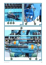
ELECTRICAL CONTROL BOX of the "AXIALE II" ED BOOM

with HYDRAULIC LOCK 

(figure 16)

Sprayer empty without hydraulic unit:

Disengage the tractor’s power take-off to not
turn the Delta pump empty.

Sprayer empty with hydraulic unit:

Engage the tractor’s power take-off the
minimum amount of time necessary to fold/
unfold the arms so as not to turn the Delta
pump empty for a long time.

Summary of Contents for AXIALE II ED Series

Page 1: ...e each use Choose correct advance speed for your field and do not make rapid or ill considered changes of direction this prolongs service life Regularly check nozzles and lines because these can becom...

Page 2: ...t of the arm stops 12 Boom height in transport position 12 Slope correction cylinder speed adjustment 14 Adjustment of the angle corrector reset option 14 Centralpartadjustment 14 Advice on boom maint...

Page 3: ...phragm anti drip device NOZAL nozzle nut mounted 1 8 turn TECHNICAL SPECIFICATIONS AXIALE SUSPENSION Boom arm Boom arm Mobile frame of the boom Level correcting ram Shock absorbers Floating or stabili...

Page 4: ...DIMENSIONS frame 16403 7606 926 2389 1939 2389 2389 1939 1939 3977 11948 5106 6606 13448 15953 14898 13898 3977 3977 24 m 27 m 28 m 30 m 32 m 33 m 5482 A C B 24 m 12 m 18 m A B C 28 m 14 m 21 m 30 m 1...

Page 5: ...13 13 32 m 6 12 10 10 10 10 12 32 m 7 9 9 9 10 9 9 9 32 m 8 8 8 8 8 8 8 8 8 33 m 6 11 11 11 11 11 11 Breakdown of the 32 m frame in terms of nozzles m 4 11 15 4 15 11 4 Breakdown of the 33 m frame in...

Page 6: ...oosen the socket 3 figure 1 Open the arm again to check the alignment Repeat the operation until the desired setting is obtained Tighten the set screw 2 IN WORK POSITION IN THE VERTICAL PLANE Open the...

Page 7: ...7 82 486 AXIALE II Booms 2 1 2 3 2 1 a 4 1 2 1 5 3 2 1 4 6 2 Detail of the ball joint...

Page 8: ...NE Turn nut 4 and bolt 5 for horizontal adjustment Note When changing the folding cylinder of the intermediate arm 2 the adjustment of the yoke C must be carried out with the boom closed and the cylin...

Page 9: ...9 82 486 AXIALE II Booms 6 2 6 7 8 5 1 3 2 C 5 4 2 3 1 5...

Page 10: ...d hook the joining shackle 6 on the ring 2 of the lock 1 FLOW LIMITERS ON INTERMEDIATE ARM figure 8 The flow limiters 1 fitted on the boom s rams are used to adapt the speed of the boom s lifting and...

Page 11: ...11 82 486 AXIALE II Booms 1 3 2 8 7 2 3 1 9 4 5 3 1 2 6 7...

Page 12: ...r B Replace the bolts Note When at rest or during road transport lower the boom so that it touches the arm support wood plates 3 along their entire length Do not attempt to lower the boom beyond this...

Page 13: ...13 82 486 AXIALE II Booms 11 1 10 12 1 2 3 A 1 B 2 3...

Page 14: ...d check that the mobile frame 3 is level arms open loosen the nuts 2 slide the sensors 1 into the opening up to the limit of illumination of the LED located on top of the sensor when the LED goes out...

Page 15: ...15 82 486 AXIALE II Booms 14 1 2 13 3 1 2 3 15 2 2 3 1 a...

Page 16: ...ng chipped areas Paint used BERTHOUD 769 077 blue aerosol Recommendations for lubrification TOTAL FINA ELF LICAL EP 2 Lubrication of the central axis KLUBER 46 MR 401 grease BERTHOUD reference 786 703...

Page 17: ...ight arm is completely opened 6 UNFOLDING THE END LEFTARM Raise switch 10 and hold it until the end left arm is completely opened 7 ADJUSTMENT OF BOOM HEIGHT Raise switch 3 and hold it to lift the boo...

Page 18: ...e completely closed 3 FOLDING THE MAINARMS Lower switch 8 and hold it until the main arms are completely closed 4 LOWER THE BOOM ONTO THE SUPPORTS Lower switch 3 and hold it until the boom rest comple...

Page 19: ...r switch the tracker is not in service the green indicator light d goes out Press and hold push button until the red indicator light c comes on the drawbar is aligned FIELD POSITION Tracker Raise swit...

Page 20: ...the handle of the tractor s double effect hydraulic distributor to adjust boom height With tracking drawbar option Raise switch and hold it to lift the boom Lower switch and hold it to lower the boom...

Page 21: ...rjust 2000 BERTHOUD 0 0 0 Electrical control box 297 x 214 mm Electrical control box 365 x 244 mm BERTHOUD BERTHOUD PROG PROG VALID VALID FIN FIN C INFO INFO DIST DIST SURF SURF 1 0 0 VOL ha VOL ha PR...

Page 22: ...t specifications or design without prior notice BER BER BER BER BERTHOUD THOUD THOUD THOUD THOUD agricole Z I de Bois Baron 1 rue de l Industrie 69220 BELLEVILLE S S FRANCE Phone 33 0 4 74 06 50 50 Fa...

Reviews: