background image


8

IMPORTANT INFORMATION CONCERNING THE INSTALLATION OF THE APPLIANCE 

The hob can be installed by itself, in an isolated position or inserted between two kitchen units or between one kitchen unit 
and a wall. Furthermore the back wall and surrounding surfaces must resist a temperature of 65 K. 
To prevent the plastic layer which covers the kitchen unit from ungluing, the glue used to join the two surfaces together must 
resist temperatures of up to 150 °C 
The installation of the appliance must be carried out according to the norms in force of the country concerned and the 
appliance must be installed in a well ventilated place.  
This appliance is not equipped with devices to remove the products of combustion. The appliance must therefore be 
connected following  the norms for installation mentioned above. Special attention must be paid to the information below 
regarding aeration and ventilation of the premises.  


VENTILATION OF THE PREMISES 

To guarantee that the appliance works correctly it is necessary that the place where the appliance is installed is continuously ventilated. 
The volume of the premises must not be less than 25 m³  and the quantity of air needed must be based on the regular combustion of 
gas and on the ventilation of the premises. The natural flow of air will take place through permanent openings made in the wall of the 
premises to be ventilated: these openings will be connected to the outside and must have a minimum section of 100 cm² ( see Fig. 2 ). 
These openings must be made in such a way that they cannot be obstructed.  


POSITION AND VENTILATION 

The cooking appliances that use gas must always remove the products of combustion via a hood linked to chimneys, chimney flues or 
via a direct connection to the outside ( see Fig. 3 ). If it is not possible to fit a hood it is possible to use a fan, fitted on the window or 
facing directly outside, which operates when the appliance is in use. ( see Fig. 4 ). In this way the norms in force of the country 
concerned regarding the ventilation of premises are strictly followed.  


BACKGUARD INSTALLATION INSTRUCTION 

1)  Remove n°2 screws fixing worktop as shown in fig.5 
2)  Place front part of the backguard and attach it from bottom side with the two removed screws (point 2) as shown in fig .6 
3)  Fix the front part of the backguard with the screws supplied with the backguard kit (fig.7) 
4)  Assemble back part with front part of the backguard and fix them with a screws supplied with the backguard kit (fig.8)  


CONNECTING THE APPLIANCE TO THE GAS SUPPLY 

Before connecting the appliance to the gas supply you first need to remove the plastic protective plug for the gas supply which 
is inserted under pressure in the gas inlet connection. To remove the plug simply unscrew it.  
Then make sure that the details shown on the label on the lower part of the case are compatible  with those of the gas supply.  
A label on the last page of this manual and on the lower part of the case  indicates the conditions for regulating the appliance: 
type of gas and pressure used. 
IMPORTANT: This appliance must be installed in accordance with the norms in force of the country concerned and it must only 
be used in a well-ventilated place.  
ATTENTION: Remember that the gas inlet connection for the appliance is  threaded 1/2 gas cylindrical male in accordance with 
the norms UNI-ISO 228-1. (Fig. 10) 


ADAPTING TO DIFFERENT TYPES OF GAS 

Before carrying out any maintenance work, disconnect the appliance from the gas and electric supply.  
 - CHANGING THE NOZZLES FOR USE WITH OTHER TYPES OF GAS: 

To change the nozzles of the burners  use the following procedure: 


Lift up the burners and unscrew the nozzles ( Fig. 9) using an adjustable spanner of 7 mm and change the nozzles with those designed 
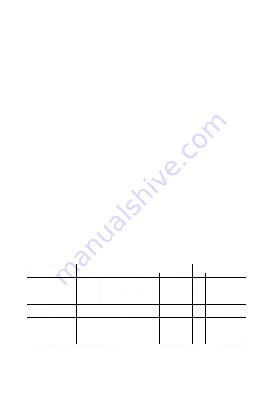
for the new gas supply according to the information given in TABLE N° 2 shown below.


ATTENTION: After carrying out the changes described above, the technician must put the label corresponding to the new gas 
supply on the appliance to take the place of the old label. This label is found in the bag containing spare nozzles.  


TABLE N°2: Adapting to different types of gas   


APPLIANCE CATEGORY:   II2H3+  

Burner 

Types of Gas 

Pressure 

Nozzle 

Diameter 

Rater Capacity 

Reduced 

Capacity 

by-pass 

Diameter 


mbar 1/100 

mm.  g/h 

l/h  kw kcal/h 

kw 

kcal/h 

1/100 

mm. 


Natural   G20 

20 

77 

95 

860 

0,48 

413 

34 reg. 

Auxiliary 

Butane   G30 

30 

50 

73 

860 

0,48 

413 

34 

 Propane 

G31 

37 

50 

71 

860 

0,48 

413 

34 


Natural   G20 

20 

101 

167 

1,75 

1505 

0,6 

516 

36 reg. 

Semi-Rapid  Butane   G30 

30 

66 

127 

1,75 

1505 

0,6 

516 

36 

 Propane 

G31 

37 

66 

125 

1,75 

1505 

0,6 

516 

36 


Natural   G20 

20 

129 

286 

2580 

1,05 

903 

52 reg. 

Rapid  

Butane   G30 

30 

87 

218 

2580 

1,05 

903 

52 

 Propane 

G31 

37 

87 

214 

2580 

1,05 

903 

52 

Dual 

Natural   G20 

20 

70 

76 

0,8 

688 

0,48 

413 

34 reg. 

Inner 

Butane   G30 

30 

46 

58 

0,8 

688 

0,48 

413 

34 

 Propane 

G31 

37 

46 

57 

0,8 

688 

0,48 

413 

34 

Dual 

Natural   G20 

20 

2x110 

419 

4,4 

3784 

1,8 

1548 

65 reg. 

Outer 

Butane   G30 

30 

2x69 

298 

4,1 

3526 

1,8 

1548 

65 


Propane 

G31 37  2x69 293  - 4,1 

3526 

1,8 

1548 65 


Summary of Contents for P92

Page 1: ...O P92 P92V FR BE INSTRUCTIONS POUR L INSTALLATION L ENTRETIEN ET page 11 L UTILISATION DES TABLES DE CUISSON ENCASTRABLES 91 5X64 cm TIPO P92 P92V DE AT MONTAGE WARTUNGS UND GEBRAUCHSANWEISUNGEN seite 15 FÜR EINBAUKOCHFLÄCHEN MIT GASBETRIEB UND GEMISCHTEM BETRIEB 91 5X64 cm TIPO P92 P92V NL INSTRUCTIES VOOR DE INSTALLATIE HET ONDERHOUD EN pag 20 HET GEBRUIK VAN GAS EN GEMENGDE INBOUWKOOKVLAKKEN 91...

Page 2: ...il riciclaggio degli apparecchi dismessi valide su tutto il territorio dell Unione Europea MANUALE TECNICO PER L INSTALLATORE NOTIZIE PER L INSTALLATORE L installazione tutte le regolazioni le trasformazioni e le manutenzioni elencate in questa parte devono essere eseguite esclusivamente da personale qualificato legge n 46 e D P R 447 Un errata installazione può causare danni a persone animali o c...

Page 3: ...utilizzando le viti fornite con il corredo dell alzatina fig 8 ALLACCIAMENTO DELL APPARECCHIO ALLA RETE GAS Prima di procedere all allacciamento dell apparecchio alla rete gas occorre innanzitutto togliere il tappo di protezione in plastica del circuito gas che e inserito a pressione nel raccordo di entrata dello stesso per rimuoverlo basta semplicemente sfilarlo Accertarsi quindi che i dati dell ...

Page 4: ... la fiamma non si spenga ATTENZIONE La regolazione suddetta va eseguita soltanto con bruciatori funzionanti a gas metano mentre con bruciatori funzionanti a gas liquido la vite deve essere bloccata a fondo in senso orario ALLACCIAMENTO ELETTRICO DELL APPARECCHIO Il collegamento elettrico deve essere eseguito in conformità con le norme e le disposizioni di legge in vigore Prima di effettuare l alla...

Page 5: ...mensioni piano cottura Tipo di piano cottura Tipo i e sezione cavo di alimentazione 91 5x64 cm bruciatori gas H05VV F 3x0 75 mm2 ATTENZIONE Nel caso di sostituzione del cavo di alimentazione l installatore dovrà tenere il conduttore di terra più lungorispetto ai conduttori di fase di circa 2 cm ed inoltre dovrà rispettare le avvertenze riguardanti l allacciamento elettrico Ingrassaggio dei rubinet...

Page 6: ...iammiferi L accensione dei bruciatori con termocoppie di sicurezza può avvenire solamente quando la manopola è sulla posizione di MASSIMO fiamma grande Durante la cottura di cibi con olio e grasso facilmente infiammabili l utilizzatore non deve allontanarsi dall apparecchio Non utilizzare spray in prossimità dell apparecchio quando è in funzione Durante l uso dei bruciatori assicurarsi che le mani...

Page 7: ... NON PROFESSIONAL USE IN HOUSEHOLDS This appliance is marked according to the European directive 2002 96 EC on Waste Electrical and Electronic Equipment WEEE This guideline is the frame of a European wide validity of return and recycling on Waste Electrical and Electronic Equipment TECHNICAL MANUAL FOR THE INSTALLER INFORMATION FOR THE INSTALLER The installation all regulations changes and mainten...

Page 8: ...t part of the backguard and fix them with a screws supplied with the backguard kit fig 8 CONNECTING THE APPLIANCE TO THE GAS SUPPLY Before connecting the appliance to the gas supply you first need to remove the plastic protective plug for the gas supply which is inserted under pressure in the gas inlet connection To remove the plug simply unscrew it Then make sure that the details shown on the lab...

Page 9: ...ply The switch must be of a suitable charge for the appliance with a minimum opening between the contacts of 3 mm Remember that the earth wire must not be interrupted by the switch Alternatively the electrical connection can also be protected by a differential switch of high sensitivity You are strongly advised to fix the special yellow green earth wire to an efficient earthing system ATTENTION Th...

Page 10: ... there is no electric current you can light the burners with matches Lighting the burners with safety thermocouples can only be carried out when the knob is on MAXIMUM large flame When cooking food with oil or fat which can easily set alight the user must not leave the appliance Do not use sprays near the appliance when it is in use When using the burners make sure that the pan handles are in the ...

Page 11: ... récupération des appareils usagés applicables dans les pays de la CE NOTICE TECHNIQUE DESTINEE A L INSTALLATEUR INFORMATIONS DESTINEES A L INSTALLATEUR L installation les réglages les transformations et les opérations d entretien décrits dans cette section doivent être exclusivement effectués par un personnel qualifié Une mauvaise installation peut provoquer des dégâts à des personnes animaux ou ...

Page 12: ... suffit simplement de le dévisser Vérifiez si les données reportées sur la plaquette d identification appliquée au bas du caisson sont compatibles avec celles du réseau de distribution du gaz La plaquette appliquée sur la dernière page de cette notice et au bas du caisson reporte les conditions de réglage de la table le type de gaz et la pression d exercice IMPORTANT La table doit être installée c...

Page 13: ...le avec une ouverture minimale entre les contacts de 3 mm Rappelez vous que le câble de terre ne doit pas être interrompu par l interrupteur En alternative le branchement électrique peut aussi être protégé avec un interrupteur différentiel à haute sensibilité Il est vivement recommandé de relier le fil de terre jaune vert à une mise à la terre efficace ATTENTION l appareil est conforme aux prescri...

Page 14: ...lisez toujours des récipients à fond plat ATTENTION En cas de coupure de courant les brûleurs peuvent être allumés avec des allumettes L allumage des brûleurs avec thermocouple de sécurité n est possible que si la manette est sur la position de MAXIMUM grande flamme Pendant la cuisson d aliments avec de l huile ou de la graisse facilement inflammables l utilisateur ne doit pas s éloigner de la tab...

Page 15: ...e in diesem Teil aufgelisteten Einstellungen Veränderungen und Wartungsarbeiten dürfen nur von qualifiziertem Personal ausgeführt werden Eine unkorrekte Montage kann Schäden an Personen Tieren und Sachen verursachen für die der Hersteller nicht haftbar gemacht werden kann Die Sicherheitsvorrichtungen oder diejenigen der automatischen Einstellung der Geräte können die ganze Lebensdauer der Anlage ü...

Page 16: ...et werden EINRICHTUNGSINSTRUKTIONEN DES WANDPFEILERS Achten darauf die Sequenz der nachstehenden Einrichtungsinstruktionen zu respektieren 1 Nehmen Sie die 2 Befestigungsschrauben des Kochplans gemäß den Hinweisen des Bild 5 weg 2 setzen den Teil vor Wandpfeiler und befestigen durch den Boden mittels der 2 Schrauben die weggenommen Punkt 2 nach Hinweisen von Abb Bild 6 3 den früheren Teil des Wand...

Page 17: ...ommen während bei mit Flüssiggas betriebenen Brennern die Schraube im Uhrzeigersinn fest angezogen werden muss ELEKTRISCHER ANSCHLUSS DES GERÄTES Der elektrische Anschluß muss entsprechend den Bestimmungen und Verfügungen der geltenden Gesetze durchgeführt werden Vor Durchführen des Anschlusses überprüfen daß Die elektrische Leistung der Anlage und der Steckdosen der maximalen Leistung des Gerätes...

Page 18: ... Ø 95 Dual Ø 140 BESCHREIBUNG SCHALTTAFEL Auf der Schalttafel wird in Übereinstimmung jeden Drehgriffs oder Taste mit einem kleinen Symbol die Funktion sichtbar gemacht Folgend sind die verschiedene Schaltungen die sich auf einem Küchenherd befinden können aufgelistet Das Symbol zeigt die Anordnung der Brenner auf der Arbeitsfläche der volle Kreis steht für die Erkennung des in Betrieb befindliche...

Page 19: ...amere Belüftung durch Erhöhen der mechanischen Saugleistung wenn es sie gibt REINIGUNG DES GERÄTES Vor jedem Reinigungsvorgang das Gerät vom Stromversorgungsnetz abschalten und den Haupthahn für die Zuführung von Gas zum Gerät schließen Reinigung der Arbeitsfläche Die Brennerköpfe die Grills aus lackiertem Stahl die lackierten Deckelchen und die Flammenteiler müssen regelmäßig mit lauwarmer Seifen...

Page 20: ...FESSIONEEL GEBRUIK Dit apparaat is voorzien van een merkteken zoals bedoeld in de Europese Richtlijn 2002 95 EG Dit apparaat is voorzien van een merkteken zoals bedoeld in de Europese Richtlijn 2002 96 EG betreffende afgedankte elektrische en elektronische apparatuur AEEA Deze richtlijn legt de bepalingen vast voor de inzameling en de recycling van afgedankte apparatuur die op heel het grondgebied...

Page 21: ... of rechtstreeks met de buitenkant verbonden kappen zie fig 3 Indien geen kap geplaatst kan worden is het gebruik van een ventilator geïnstalleerd op een venster of rechtstreeks met de buitenkant verbonden toegestaan de ventilator moet tezamen met het apparaat in werking gesteld worden zie fig 4 mits de nationale normen inzake de ventilatie van de lokalen in acht genomen zijn INSTALLATIE VAN DE PL...

Page 22: ...g naar rechts gedraaid en geblokkeerd moet worden ELEKTRISCHE AANSLUITING VAN HET APPARAAT De elektrische aansluiting moet verricht worden met inachtneming van de bestaande normen en wetsbepalingen Alvorens tot de elektrische aansluiting over te gaan controleer of het elektrisch draagvermogen van de installatie en van het stopcontact passend is bij het maximum vermogen van het apparaat zie het typ...

Page 23: ... 70 Snel Ø 95 Vlamkroon Ø 130 BESCHRIJVING BEDIENINGSPANEEL BESCHRIJVING VAN HET BEDIENINGSPANEEL Op het bedieningspaneel wordt overeenkomstig elke draaiknop of toets de functie weergegeven door middel van een klein symbool Vervolgens worden de verschillende bedieningen aangeduid die u kan vinden op een fornuis het symbool duidt de schikking van de branders op het werkvlak aan het gevulde bolletje...

Page 24: ...nde ventilatie nodig maken bv het openen van een raam of een meer efficiënte ventilatie door vermeerdering van het vermogen van de mechanische opzuiginrichting indien deze bestaat SCHOONMAAK VAN HET APPARAAT Alvorens over te gaan tot schoonmaak van het apparaat trek de stekker uit het stopcontact en sluit de algemene gaskraan Schoonmaak van het werkvlak maak de brandershoofden de geëmailleerde sta...

Page 25: ...25 Fig 1 Fig 2 Fig 3 Fig 4 ...

Page 26: ...26 Fig 5 Fig 6 Fig 7 Fig 8 Fig 9 Fig 10 ...

Page 27: ...27 Fig 11 Fig 12 Fig 13 Fig 14 Fig 15 ...

Page 28: ...28 Cod 310518 ...

Reviews: