background image


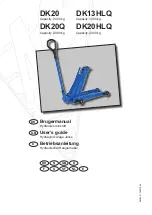
DK20, DK20Q, DK13HLQ

 DK20HLQ 


WARNING - 

  safe usage instructions

  1.  

Study, understand and follow all instructions before 

operating this jack.


2. 

Do not exceed rated capacity.


3. 

Use only on hard level surface.


4. 

It is recommended to brake and chock the vehicle.


5.  

Do not move or transport the vehicle while on the 

jack.


6.  

Lifting device only. Immediately after lifting, sup-

port the vehicle with support stands.


7.  

Lift only on areas of the vehicle as specified by 

the vehicle manufacturer, and only centrally on the 

lifting saddle.


8.  

No person shall remain in, on, or get bodily under 

a load that is being jacked or is supported only by 

a jack.


9.  

Only original accessories and spare parts shall be 

used.


10. 

No alterations shall be made to this jack.


11.  

Failure to follow these warnings may result in per-

sonal injury and/or property damage.

Assembly

Mount plastic handle on tube lever with inner projec-

tion to fit into slot. Push tube lever into handle until 

screw and nut can be mounted (use a rubber hammer 

to adjust handle position).

Then place lever in tipping gear, and secure it with tip-

ping gear screw fitting into slot in tube lever. 

Use

Lifting: 

Activate lever tube up and down using full 

strokes.

Lowering:

 Pull lever tube up, then slowly turn counter 

clockwise. 

Maintenance

Maintenance and repair must always be carried out by 

qualified personnel.

Daily:

 Inspect jack for damages.

Monthly: 

Lubricate all mechanical parts with a few 

drops of oil.

Oil refill: 

Pump with cylinder is a closed system and 

refilling of oil is normally not necessary. In order to refill 

oil it is necessary to demount the hydraulic unit:

GB

1. 

Unfasten screw (23) through hole in base frame. 

2. 

Release and lower the jack completely.

3.   

Keep lever vertically and block piston rod (34) in the 

inmost position by means of a screw or nail through 

hole in release bracket (42). Mind the inner spring!

4.   

Remove lever tube and tipping gear as well as the 

two screws (6) on top of lifting frame.

5.   

Now the hydraulic unit is loose and can be removed 

up front from the lifting frame.

6.   

Assembly takes place in reverse order. Pump the 

jack half-way up in order to ease mounting of the 

last screw (23).

Correct oil level is up to lower edge of filling hole (27) 

with the cylinder vertical and the piston rod pushed 

completely in. Too much oil causes poor pumping.

Quantity of oil:

  DK20, DK20Q and DK13HLQ:  

0,3 l.


DK20HLQ:  


0,5 l.

Any good hydraulic oil of viscosity ISO VG 15 can be 

used.  

Never use brake fluid!

Safety Inspection

According to national legislation - minimum once a 

year though - the jack must be inspected by a profes-

sional: damages, wear and tear, adjustment of the 

safety valve, hydraulic unit for leakages.  

Possible faults and how to overcome them

1.

   The load is dropping occasionally: Verify the play 

between release bracket (42) and lever tube. Adjust 

the two nuts (10) until the play is 1-2 mm, irrespec-

tive of the lever tube position (vertical or horizontal).

2.   

The jack does not lift to maximum position: refill 

with oil.

3.   

The load is dropping: leaking pump valves or worn 

seals. Inspect the valve seats + balls under plug 

(30) and change seals in lifting cylinder.

4.   

The hydraulic unit is leaking: exchange worn seals 

with repair kit 0906000.
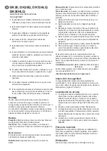
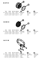
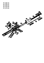
Spare parts

Replace worn or broken parts with genuine jack manu-

facturer supplied parts only. All major parts may not be 

provided after discontinuation of a model.

Destruction

Oil must be drained off and legally disposed of.

Summary of Contents for 114136

Page 1: ...Bedienungsanleitung Bedienungsanleitung Artikelnummer 114136 159582 167445 Sprachen nl en fi fr de no ru es sv BERNER_Bedienungsanleitung_Bedienungsanleitung_65397 PDF _de pdf 2016 09 23...

Page 2: ...Hydraulisk donkraft User s guide Hydraulic Garage Jacks Betriebsanleitung Hydraulischer Rangierheber DK GB D DK F N S GB SF D NL DK20 Capacity 2 000 kg DK20Q Capacity 2 000 kg DK13HLQ Capacity 1 300...

Page 3: ...er et lukket system og efterfyldning er normalt ikke n dvendigt Efterfyldning af olie kr ver udtagning af den komplette pumpe 1 L sn skrue 23 gennem hul i k reramme 2 Udl s og s nk l fterammen helt i...

Page 4: ...t GB 1 Unfasten screw 23 through hole in base frame 2 Release and lower the jack completely 3 Keep lever vertically and block piston rod 34 in the inmost position by means of a screw or nail through h...

Page 5: ...der Regel nicht notwendig Zum Nachf llen des ls muss die gesamte Pumpe ausgebaut werden 1 L sen Sie die Schraube 23 durch das Loch im Fahrrah men 2 L sen Sie den Heberahmen und senken Sie ihn ganz nac...

Page 6: ...faire l appoint d huile Toutefois le cas ch ant vous devez retirer la pompe compl te pour faire l appoint d huile 1 Desserrez la vis 23 travers le trou du cadre 2 D tachez et abaissez le cadre de lev...

Page 7: ...och cylinder r ett st ngt system och efterfyllning r normalt inte n dv ndig Efterfyllning av olja kr ver att hela pumpen tas ur 1 Lossa skruven 23 genom h let i k rramen 2 L s ut och s nk lyftramen nd...

Page 8: ...dellytt koko pumpun irrot tamista 1 L ys ruuvia 23 ajorungon rei n kautta 2 Vapauta ja laske nostorunko kokonaan pohjaan 3 Pid kahvaa vaakasuorassa ja lukitse pumpun m nt 34 sisimp n asentoon asettama...

Page 9: ...n een gesloten systeem en navullen is normaal niet nodig Bijvullen met olie vereist het verwijderen van de vol ledige pomp 1 Maak de schroef 23 los door de opening in het rijframe 2 Zet het hefframe i...

Page 10: ...ceite Si hubiera que hacerlo es necesario desmontar la bomba al completo 1 Suelte el tornillo 23 a trav s del orificio que hay en el bastidor de recorrido 2 Suelte el bastidor de elevaci n y h galo ba...

Page 11: ...e 9 36 003 00 36 003 00 36 003 00 36 003 00 2 Hjulgaffel Wheel fork Radgabel 10 36 006 00 36 006 00 36 006 00 36 006 00 1 Sadel Saddle Sattel 11 36 007 00 36 007 00 36 007 00 36 007 00 2 Hjul fast Whe...

Page 12: ...nelse Description Bezeichnung 36 008 00 36 008 00 36 008 00 36 008 00 Hjul svingbar Wheel fixed Rad fest 1 01 377 00 01 377 00 01 377 00 01 377 00 1 O ring O ring O ring 2 36 008 10 36 008 10 36 008 1...

Page 13: ...91 050 00 91 070 00 91 070 00 91 075 00...

Page 14: ...00 02 183 00 02 183 00 2 Kugle 2 5 Ball Kugel 20 02 224 00 02 224 00 02 224 00 02 224 00 2 Seegerring Circlip Seegerring 21 02 292 00 02 292 00 02 292 00 02 292 00 2 Kugle 6 5 Ball Kugel 22 02 294 00...

Page 15: ...HYDRAULIK DIAGRAM HYDRAULIC CHART HYDRAULISCHES DIAGRAMM DK GB D...

Page 16: ...eichnung 36 014 00 1 GS1 gummisadel GS1 rubber cushion GS1 gummiauflage Pos Art No Pcs Ben vnelse Description Bezeichnung 36 016 00 1 FDK1 forl nger FDK1 extension FDK1 Verl ngerung Pos Art No Pcs Ben...

Page 17: ...idraulicos DK20 DK20Q DK13HLQ DK20HLQ son conforme con las directrices sobre m quinaria Di rectiva 2006 42 EC y EN1494 incl enmiendas y en conformidad con las directrices nacionales relevantes Hydraul...

Reviews: