


20. Slide the Top Guide Sleeve (Key No. 20) over the
Shaft and rest it on the Thrust Washer.
21. Slide the Shaft Lock Washer (Key No. 21) onto the
Top Guide Sleeve and lock it with an M8 Allen Screw
(Key No. 6).
22. Install the Standard Guide Housing (Key No. 9). Seat
it on the Delivery Stage Plate (Key No. 17) by gently
tapping it with a rubber mallet.
NOTICE: The bearing is not centered end-to-end in
the Guide Housing. Make sure that the Guide Housing
goes on to the Shaft with the short (9.25mm or 3/8”)
end of the Guide Housing going first, as shown in the
exploded view, Page 10.
23. Mount the Discharge (Key No. 24) on the Guide
Housing by gently tapping it with a rubber mallet.
24. Hook the four Straps (Key No. 25) onto the Discharge
and fasten them to the Suction Bracket Assembly with
Lock Washers (Key No. 27) and M12 Hex Head Bolts
(Key No. 28).
NOTICE: Tighten the four Straps evenly to 6.5 kgm
(47 ft.-lbs.) torque.
25. Install the Outer Strainer (Key No. 29) and Cable
Guard (Key No. 30) with two 4 mm Washers (Key No.
31) and M4 Screws (Key No. 32).
26. Remove the pump from the fixture.
27. Check the axial clearance of the pump shaft (2.5 mm
to 3 mm. or 3/32” to 1/8”).
The pump is ready for installation.
Table VI: Intermediate Guide Housing Locations
Number of
Number of
Stages
Guide Housings Required
0 - 12
0
13 - 24
1 at Midpoint of Shaft
25 - 37
2 at 1/3 and 2/3 Length of Shaft
Space Intermediate Guide Housings evenly.
9
PREVENTIVE MAINTENANCE
To avoid major repairs, make the checks listed below every 4 to 6 months.
TEST
1.
Measure and record the standing
water level (from top of well
casing).
2.
Measure electrical resistance
between motor leads and well
casing with motor cold.
3.
Check pump flow capacity
(gallons per minute).
4.
Check pump discharge pressure
(PSI) at operating conditions.
5.
Check drawdown level (in feet)
from standing water level.
6. Measure voltage across motor
leads while pump is operating.
RESULT SHOULD BE
1. Reference number.
2.
See motor manual.
3.
At least 90% of readings at
installation.
4. At least 90% of readings at
installation.
5. High enough so that pump does
not break suction.
6.
Within ±10% of rated voltage.
POSSIBLE INDICATIONS
1.
To aid in monitoring pump
performance.
2.
See motor manual.
3.
Lower readings may indicate
pump needs repair.
4.
Lower reading indicates pump
wear, increased friction losses, or
change in standing water level in
well.
5.
Cavitation can damage pump;
increased drawdown may
indicate reduced well flow.
6.
If voltage is more than 110% or
less than 90% of rated voltage,
consult power company.
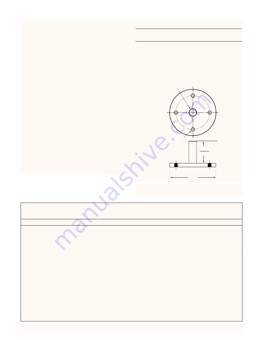
2.875"
2.869"
6.0"
1/2 - 20 UNF-2B
4.38" DIA. B.C.
4 Holes
1.00" Dia.
Figure 8: Assembly fixture dimensions for 6” motor;
stickup is motor height.