


Anchor power cable to pipe every 20 feet with adjustable
steel band clamps. Protect insulation from clamps with
pieces of split rubber hose inserted between clamps and
cable. Attach cable to pipe halfway between clamps with
waterproof tape (Scotch No. 33 or equivalent).
Submergence
Be sure the pump is always submerged, even at extreme
pumping rates. Install pump at least 10 to 20 feet below
the lowest "drawdown" water level and at least 5 feet
above bottom of well.
Check Valves
Every 6S/E6S pump is factory equipped with an internal
check valve in the pump discharge. No additional check
valve is required near the pump.
Install check valve in discharge pipe, not more than 25 feet
above pump. For 6" and larger submersible pumps
installed more than 600 feet deep, install a second check
valve at the pipe joint nearest to the half-way point
between pump and ground level.
NOTICE: To avoid water hammer and pipe breakage,
distance from first check valve to second check valve
should not equal distance from second check valve to
ground level.
Well and Pump Test
Check and record static water level of well before starting
tests. Before making final piping connections, test flow
rate, capacity, and condition of well.
NOTICE: Do not operate pump with discharge valve
closed. Operate pump only within pressure and flow limits
of operating range established by performance curve.
NOTICE: If sand is present in discharge, allow pump to
run with discharge completely open until water is clear. If
loud rattling noises develop, pump is probably cavitating.
Gradually close discharge valve until rattling stops.
INSTALLATION -
ELECTRICAL TESTS
Risk of high voltage electrical shock
when testing. Can stun, burn, or kill.
Only qualified electricians should perform these tests.
When testing, use all normal precautions for the
voltages involved.
Electrical test of motor, cable, connections
The cable and splices can be damaged as the pump is
lowered into the well. To electrically test them, attach one
lead of ohmmeter to pipe. Attach other lead to each cable
lead in turn. See motor owner's manual for required
resistance in a good motor. A low reading indicates that
cable or splice has developed a leak to ground. Remove
pump from well and correct problem before proceeding
with installation.
Measure electrical resistance between motor leads and
well casing when motor is cold.
Voltage test (Figure 2)
Low or high voltages can cause motor failure. While pump
is operating, check voltage across each pair of leads at
motor controller. Readings more than 10% above or below
rated nameplate voltage can damage pump; correct before
placing pump in service. Test as follows:
1. Disconnect main power supply and open controller.
2. Connect power and start pump. For 3-phase motors,
read voltage across three pairs of leads (L1 – L3, L3 –
L2, L2 – L1) while pump is operating. For single phase
motors, read voltage across L1 and L2 while pump is
operating. Voltage should be within ±10% of motor
nameplate rated voltage. If not, consult power
company.
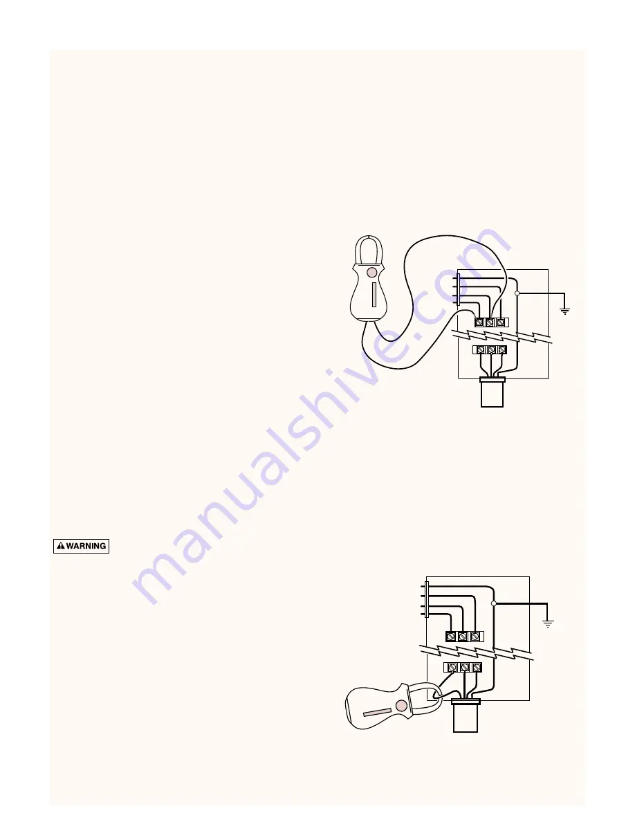
Load current test (Figure 3)
Load current should be obtained on each motor lead at the
controller. Partially close pump discharge valve (keep
pressure and flow within specified operating range) until
maximum amp reading has been obtained. Compare
reading with motor nameplate rating. If reading is 15% or
more over rated load, check for incorrect voltage in supply
line or overload due to abrasives in pump. Find and correct
problem before putting pump in service.
4
L3
L2
L1
G
To Pump
Incoming
Power
Ground
Controller
Figure 2: Voltage Test
L3
L2
L1
G
To Pump
Incoming
Power
Ground
Controller
Figure 3: Load Current Test