Owner’s Manual
BWC EXCEL 10 Turbine
Page 22
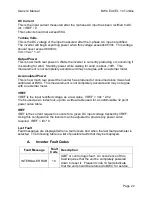
DC Current
This is the input current measured after the 3-phase AC input has been rectified to DC.
Idc = IREF / 9
This current should not exceed 58A.
Turbine Volts
This is the DC voltage of the input measured after the 3-phase AC input is rectified.
The inverter will begin exporting power when this voltage exceeds 85Vdc. This voltage
should never exceed 690Vdc.
Vdc = Vac * 1.41
Output Power
This is how much real power in Watts the inverter is currently producing or consuming if
it is waiting for wind. Standby power while waiting for wind is about -10W. This
measurement is not completely accurate and may not agree with an external meter.
Accumulated Power
This is how much real power the inverter has produced or consumed since it was last
calibrated at BWC. This measurement is not completely accurate and may not agree
with an external meter.
VREF
VREF is the input rectified voltage as a raw value. VREF = Vdc * 2.52.
Vref is used as an index look-up into a virtual table used for a customizable 32 point
power curve table.
IREF
IREF is the current request in counts for a given DC input voltage tracked by VREF.
Using this configuration the inverter can be adjusted to provide any power curve
required. IREF = Idc * 9
Last Fault
Fault messages are displayed when a fault occurs and when the last fault parameter is
selected. The following table is a list of possible faults that may be displayed.
A.
Inverter Fault Codes
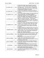
Fault Message
Fault
Code
Description
INTERNAL ERROR
10
IGBT or control logic fault. An occurrence of this
fault requires that the unit be completely powered
down to reset it. Frequent code 10 faults indicate
that the unit should be returned to BWC for service.


