Owner’s Manual
BWC EXCEL 10 Turbine
Page 20
withstanding input line to ground surges of about 6kV at 3kA. Contact your distributor or
BWC for application specific lightning surge suppression solutions.
E.
Inverter Operation
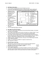
This equipment is a UL 1741 certified Utility Interactive Inverter and complies with the
requirements of IEEE1547 which is the standard for interconnecting distributed
resources with electric power systems. It will not operate in an off-grid or backup power
configuration.
The normal operation of the inverter is as follows: When single phase utility power is
applied to the output of the inverter, the display will power up and a message stating
that the unit is initializing is shown. If there are no faults, i.e. grid voltage and frequency
are in tolerance, a countdown timer set for 5 minutes (300 seconds) starts before the
inverter is ready to transfer power to the utility grid. The inverter will automatically
transfer power to the utility when AC voltages in the range of 30VAC to 400VAC are
present at the Turbine input.
As the heatsink heats up after exporting significant power for a period of time the
internal cooling fans will activate. The inverter is be able to operate at full power
continuously if provided with adequate ventilation and the local ambient temperature
stays below 45ºC (113ºF). If the ventilation is compromised or the heatsink temperature
exceeds 60°C, the inverter will automatically reduce its output power.
F.
Touch Screen Display
The touch screen display located on the front panel of the enclosure provides manual
over-
ride and status of the inverter’s operation. The touch screen display also provides
a Stop and a Reset button. The Stop button is used when it is desired to disconnect the
inverter from the power grid and the wind turbine. After Stop is pressed the inverter will
remain in a powered-up stand-by mode until Reset is pressed or Grid voltage is
removed. When Reset is pressed the inverter will resume normal operation.
The status of the inverter’s operation is shown on the lines one and two of the display.
The following table lists the status messages that may appear.
Status Message
Description
Waiting
Initializing
The inverter has been reset or that the 5 minute countdown delay
is in progress
Waiting
For Wind
The voltage from the turbine is lower than the factory set auto-
start voltage threshold
AC Running
The active rectifier is regulating the internal DC Boost voltage
Running
The inverter is transferring power to the utility grid
Fault
A fault has occurred. See fault messages
Manual Stop
Press Reset
The manual stop button has been pressed
Fault Limit
Press Reset
Three faults have occurred in an hours time
Disconnected
Indicates that a communication problem exists between the

