


12
put the ramp of the gas valve back in place and screw the nut
reposition the previously removed components
power up the boiler and open the gas tap again.
Adjust the boiler as explained in paragraph “3.9 Adjustments” and paragraph
“3.10 Gas valve calibration”.
b
Conversion must be carried out by qualified personnel.
b
After the transformation, apply the new rating plate included in the kit.
3.12 Range rated
This boiler can be adapted to the heating requirements of the system, in fact it
is possible to set the maximum delivery for heating operation of the boiler itself:
power up the boiler
set the parameter
310
Range rated
Set the maximum heating value (rpm) and confirm.
0
0
7
.
rpm
0
0
7
.
rpm
confirm
MAX
rpm
Record the new set value in the table on the back cover of this manual. For
subsequent controls and adjustments, refer to the set value
.
b
The calibration does not entail the ignition of the boiler.
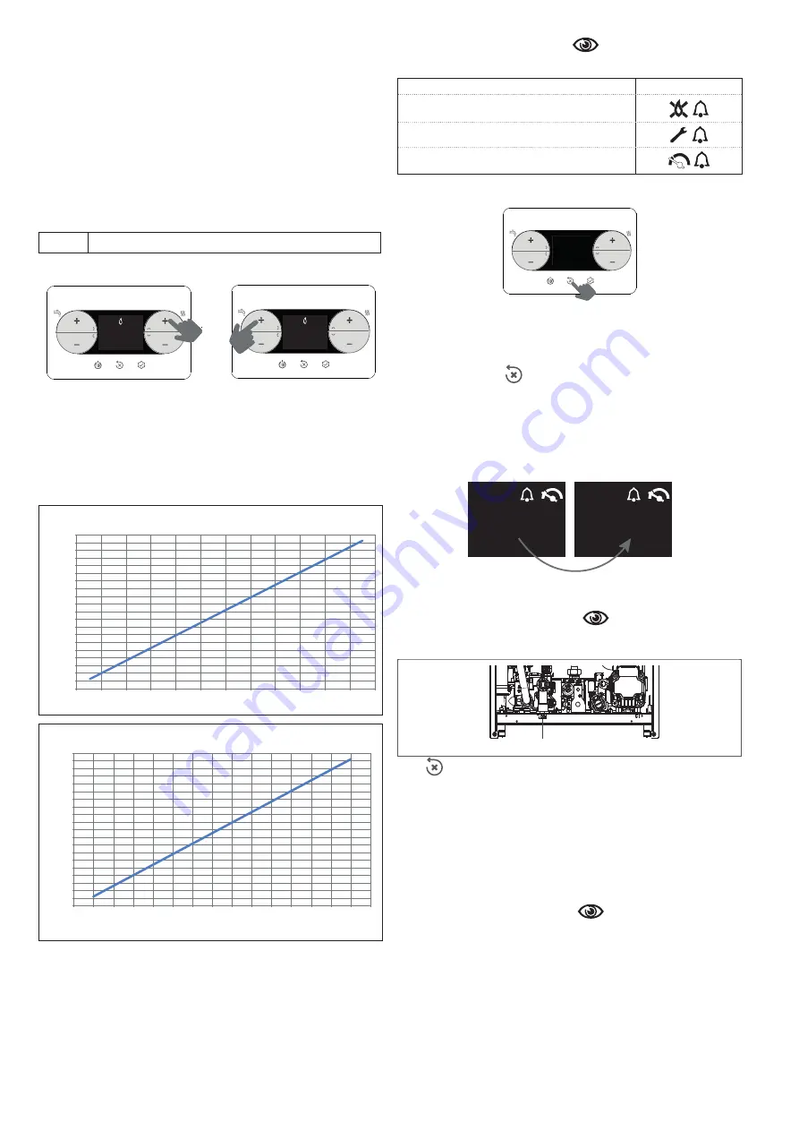
The boiler is supplied with the adjustments shown in the technical data table.
Depending on plant engineering requirements or regional flue gas emission
limits however, this value can be modified by referring to the graphs below.
1000
1400
1800
2200
2600
3000
3400
3800
4200
4600
5000
5400
5800
6200
6600
7000
7400
7800
8200
8600
9000
2
4
6
8
10
12
14
16
18
20
22
24
26
Gi
ri
ve
n
�
la
to
re
(r
.p
.m
.)
Portata termica (kW)
Heat input curve - fan rotations - Ciao 25C f
fan rotations (r
.p.m.)
heat input (kW)
fan rotations (r
.p.m.)
1000
1400
1800
2200
2600
3000
3400
3800
4200
4600
5000
5400
5800
6200
6600
7000
7400
7800
8200
8600
9000
2
4
6
8
10
12
14
16
18
20
22
24
26
28
30
32
Gi
ri
ve
n
�
la
to
re
(r
.p
.m
.)
Portata termica (kW)
Caldaia CIAO 30C f
Heat input curve - fan rotations - Ciao 30C f
heat input (kW)
3.13 Faults and reporting
If there is a fault, an error code “Axx” is shown on the display.
In certain cases, the error code is accompanied by an icon:
FAULTS
ICONS DISPLAYED
flame failure A10
all faults except flame failure and water pressure
water pressure
Reset function
To reset boiler operation in the event of a fault,
press:
> 2 sec
Res
If the correct operating conditions have been restored, the boiler will start up
again automatically.
In the presence of a remote control, a maximum of 5 consecutive unlocking
attempts are available.
I
n this case, by pressing
the boiler restores the initial attempts.
b
If the attempts to reset the boiler do not work, contact the Technical As
-
sistance Centre.
Fault A41
If the pressure value falls below the 0.3 bar safety value, the boiler shows the
fault code A41 for a transitory time of 10 min. If the fault still persists after this
time, fault code
A40 will appear.
4
A
1
4
A
0
With fault A40 on the boiler it is necessary to:
- open
the filling tap (
A
) turning it counterclockwise
- access the Info menu (
“4.3 INFO menu
”, item I018), to check that the
pressure value reaches 1-1.5 bar
- close
the filling tap (
A
)
, making sure you hear the mechanical click
.
A
Press
to restore operation.
After filling, run a venting cycle. If the pressure
drop is very frequent, contact the Technical Assistance Centre
.
Fault A60
The boiler is working normally, but does not provide any stability of the domestic
hot water temperature that, in any event, is supplied at a temperature of around
50°C. The intervention of the Technical Assistance Centre is required.
Fault A91
The boiler has a self-diagnosis system that signals the need to clean the primary
heat exchanger on the basis of the total number of hours in certain operating
conditions (alarm code A91).
Fault A91 occurs when the counter exceeds the value of 2500 hours; this value
can be checked in the “4.3 INFO menu
”, item
I015
(visualization/100,
example 2500h = 25)
After cleaning (using the special kit supplied as an accessory), reset the total
hours counter by bringing parameter 312 = 1.
NOTE: The meter resetting procedure should be carried out after each in-dep-
th cleaning of the primary exchanger or if this latter is replaced.
3.14 Replacing the board
If the check and adjustment board is replaced, it may be necessary to repro
-
gram the configuration parameters. In this case, refer to the parameters table
to see the board default values, the factory set values, and the personalised
values. The parameters that must be checked and reset if necessary after repla-
cing the board are: 301 - 302 (SERVICE) - 306 - 307 - 308 - 309 - 310.


