background image

26

TIVANO WALL - Uso / Use

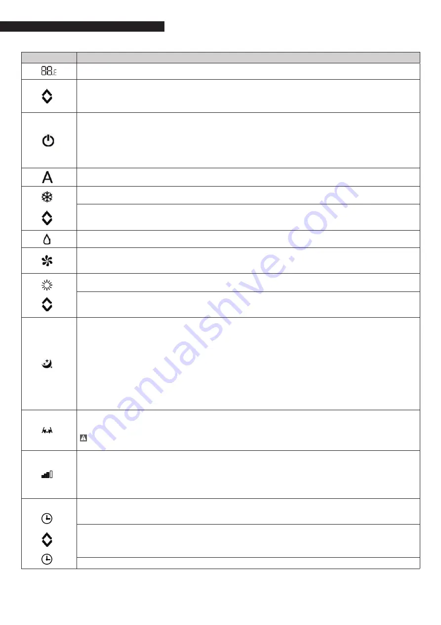
KEY / DISPLAY

OPERATION

When the appliance is on, the setpoint is shown on the 3 digits of the display.

It is possible to adjust the setpoint between 16 and 31°C at which the cooler-radiator will adjust the 

temperature environment.

Do not set temperatures that are too high or too low as this could lead to health risks or an unne-

cessary waste of energy.

Switching the appliance on and off

It  is  possible  to  switch  the  appliance  on  or  off  (stand-by)  by  pressing  the  specific  button.  The  

control system of the appliance is equipped with a memory, so settings won’t be lost if the ap-

pliance is switched off or in the event of low voltage (with the exception of the fan, when the unit 

is turned on, it is at the maximum speed). The button must be used to activate or deactivate the 

appliance for short periods of time. If you plan to keep the device out of service for a long time  

remember to deactivate it by disconnecting the power or removing the power plug

Not used

Cooling only mode

In this mode, the appliance dehumidifies and cools the room. 
It is possible to set the desired temperature between 16 and 31°C and, if such temperature is  

lower than the room temperature, the fan starts up after maximum three minutes and the appliance 

starts dispensing cool air, maintaining ventilation active even if the setpoint has been reached.

Not used

Ventilation only mode

With this function fan is active and the water valve is closed. 

it is possible to choose fan speed.

Heating only mode

In this mode, the appliance heats the room. 
It is possible to set the desired temperature between 16 and 31°C and, if such temperature is  

higher than the room temperature, the fan starts up after maximum three minutes and the 


appliance starts dispensing warm air.

Nocturnal well-being button 

In this mode, ventilation is set on minimum speed.

This mode should be activated right before going to sleep.

-  In cooling mode, the set temperature is risen by 1°C after one hour and by another degree after  

  two hours.  After the second hour, the temperature is no longer changed and, after six hours, the  

  appliance is put in stand-by.   

-  In heating mode, the set temperature is lowered by 1°C after one hour and by another degree  

  after two. After the second hour, the temperature is no longer changed and, after six hours, the  

  appliance is put in stand-by.

This function is not available for ventilation only and can be exclu-

ded any time (ideally once awake) by pressing the button again. 


If the Timer has also been set, the appliance will turn off at the set time. 

Control of air flow direction 

By pressing the specific button, it is possible to select the continuous oscillation of the mobile air 

outlet flap - in such case, the symbol on the display is lit - or to block it in any position.


IMPORTANT: 

The 

mobile 

flap 

must 

never 

be 

moved 

manually. 

In 

cooling  

mode the position of the flap is reset every 30 minutes, in order to prevent dew from forming.

Fan speed control

By pressing this button, the speed changes according to the following sequence: Minimum, Medium, 

Maximum. 

The higher the speed, the better the performance, though the appliance will be more noisy.   

It is not possible to control the speed while in nocturnal well-being mode, as the appliance can only 

work in low speed.

Timer mode setting 

The appliance offers Users the chance to program its activation and deactivation according to their 

needs. 
While the conditioner is on, it is possible to program the switch-off time by pressing the Timer but-

ton and setting the number of hours (1 to 24) after which the appliance will be put in stand-by. 

When the conditioner is off, it is possible to program the switch-on time by pressing the Timer  

button and setting the number of hours (1 to 24) after which the appliance will start-up.
Press the button to confirm.

Summary of Contents for 20148838

Page 1: ...TIVANO WALL Manuale Installatore Installation and Operation Manual EN IT Manuale Installatore Installation and Operation Manual...

Page 2: ...rective 2014 35 UE RoHS Directive 2011 65 UE WEEE Directive 2012 19 UE Gamma Range Modello Codice TIVANO WALL 27 20148838 TIVANO WALL 41 20148839 TIVANO WALL 57 20148840 Model Code TIVANO WALL 27 2014...

Page 3: ...IVANO WALL 27 41 57 23 3 4 Descrizione del funzionamento con telecomando o display touch screen TIVANO WALL 27 41 57 24 3 5 Utilizzo dell apparecchio 27 4 MANUTENZIONE 4 1 Manutenzione 28 4 2 Pulizia...

Page 4: ...degli infortuni Rispettare le leggi in vigore nel Paese in cui viene installata la macchina relativamente all uso e allo smaltimento dell imballo dei prodotti impiegati per pulizia e manutenzione e p...

Page 5: ...without the authorisation and directions of the manufacturer Do not stand sit and or place objects on the unit Do not pull detach or twist the electrical wires coming out of the unit even when the uni...

Page 6: ...difficoltosa qualsiasi operazione di installazione e manutenzione The technical tag shows all technical and performance data of the unit Should the tag get lost please ask for a duplicate tag from th...

Page 7: ...h 320 430 540 Portata d aria med Air flow rate med m3 h 250 340 410 Portata d aria min Air flow rate min m3 h 140 230 310 Tensione di alimentazione Supply voltage V ph Hz 230 1 50 230 1 50 230 1 50 Po...

Page 8: ...carico 1 8 Charts of Water flow Pressure drop Perdita di carico kPa Pressure drop kPa Portata d acqua kg h Water ow kg h 27 41 57 Perdita di carico kPa Pressure drop kPa Port W 0 5 1 2 4 8 16 30 150 7...

Page 9: ...so il ventil convettore viene posto in stand by AIR Sonda aria DISPLAY cablaggio display pannello H2 water temperature probe 10 k M1 fan motor DC inverter Y1 water solenoid valve 230V 50Hz 1A powered...

Page 10: ...come into contact with water in environments with oil mists in environments subject to high frequencies Make sure that the wall on which you intend to install the unit has an appropriate structure an...

Page 11: ...ing bracket B Coil water inlet C Coil water outlet D Condensate drain E Connector terminal F Cable clamp 20 mm 20 mm 120 mm min 2000 mm pavimento floor 2 5 Distanze minime di installazione Nella figur...

Page 12: ...ta esagonale presenti ai lati del pannello frontale per poter rimuovere il pannello frontale estetico A FIANCHETTI B PANNELLO FRONTALE ESTETICO 2 6 Opening of aesthetic parts for installation For desc...

Page 13: ...alto rimuovendo prima le due viti che fissano al fianco sinistro la struttura del display se presente A FILTRI B FIANCHI LATERALI 3 Wheels and rise the filters 4 Remove the fixing screws of side pane...

Page 14: ...alla dima di installazione in dotazione riportata successivamente A CASSETTA DA INCASSO B TUBAZIONI IDRONICHE DI RACCORDO C TUBO DRENAGGIO CONDENSA D TIVANO WALL 2 7 Wall mount For smooth installatio...

Page 15: ...fe e la sua stabilit 6 Fare attenzione all inclinazione del ventilconvettore rispettando la corretta inclinazione come in figura a fondo pagina 1 3 2 4 G 1 NO A TASSELLI B STAFFE 1 Use the paper templ...

Page 16: ...16 TIVANO WALL Installazione Intallation 2 8 Dima di installazione quotata 2 8 Installation template measured...

Page 17: ...17 TIVANO WALL Installazione Installation...

Page 18: ...alla laterale sotto gli attacchi idraulici Se possibile fare defluire il liquido di condensa direttamente in una grondaia o in uno scarico di acque bianche In caso di scarico nella rete fognaria si co...

Page 19: ...Connect the drain connection of the drain pan that collects the condensate fluid to a hose and tighten it properly Make sure the drip guard extension is present and that it has been properly installe...

Page 20: ...riferiti ad una lunghezza massima delle linee pari a 15 m I cavi devono essere di tipo adeguato al tipo di posa in accordo con le norme CEI in vigore 27 41 57 SEZIONE CONDUTTORE DI ALIMENTAZIONE FASE...

Page 21: ...cciavite sullo sfiato dell attacco batteria posto pi in alto vedi figura sotto Quando comincia ad uscire acqua dalle valvole di sfiato dell apparecchio chiuderle e continuare il caricamento fino al va...

Page 22: ...ere fatto funzionare utilizzando i tasti del display touch screen a bordo macchina It is possible to select the various modes by pressing the buttons see Description of machine functioning para graph...

Page 23: ...ione del flusso d aria Tasto controllo della velocit del ventilatore Tasto impostazione funzione Timer 1 Tasto impostazione funzione Timer 2 Sensore di luminosit Termometro digitale 1 7 barrette rosse...

Page 24: ...serve per l attivazione e la disatti vazione dell apparecchio per brevi periodi In caso di prolungato arresto dell apparecchio questo deve essere disattivato staccando l interruttore generale o toglie...

Page 25: ...le non deve mai essere forza to manualmente In raffrescamento la posizione del deflettore viene resettata ogni 30 min per evitare formazione di rugiada Controllo della velocit del ventilatore Premendo...

Page 26: ...this mode ventilation is set on minimum speed This mode should be activated right before going to sleep In cooling mode the set temperature is risen by 1 C after one hour and by another degree after...

Page 27: ...azione servirsi sempre del comando apposito Nel caso vi fossero perdite d acqua dall apparecchio necessario spegnerlo immediatamente e togliere l alimentazione elettrica Chiamare quindi il Servizio Te...

Page 28: ...leaning Disconnect the unit from the power supply before each cleaning and maintenance intervention by setting the main power supply switch to off Wait for the components to cool down in order to avoi...

Page 29: ...he frequency is semiannual in domestic environment Pulizia setti filtranti aspirare la polvere dai filtri con un aspirapolvere lavare sotto acqua corrente senza utilizzare detergenti o solventi i filt...

Page 30: ...y Non possibile attivare nessun funziona mento dell apparecchio CP Contatto presenza CP aperto L apparecchio si attiva solo se il contatto chiuso Verificare la connessione dei mor setti LAMPEGGIANTE T...

Page 31: ...e il corpo valvola e verificare se si ripristina la circolazione dell ac qua Controllare lo stato di funziona mento della valvola alimentandola separatamente a 230 V Se si dovesse attivare il problema...

Page 32: ...Leaks at the valves unit Check the condition of the gaskets There is dew on the front panel Detaches thermal insulation Check the correct positioning of the thermal and acoustic insula tions paying p...

Page 33: ...33 TIVANO WALL Allarmi Troubleshooting...

Page 34: ...34 TIVANO WALL Allarmi Troubleshooting...

Page 35: ...35 TIVANO WALL Allarmi Troubleshooting...

Page 36: ...onamentodituttalasuaproduzione lecaratteristicheestetiche edimensionali idatitecnici gliequipaggiamentiegliaccessori possonoesseresoggettiavariazione The manufacturer strives to continuously improve a...

Reviews: