5
ASSEMBLY
IMPORTANT: TORQUE ALL BOLTS ACCORDING
TO TORQUE SPECIFICATION TABLE (SEE TABLE
OF CONTENTS) WHEN STATED: TIGHTEN
FIRMLY. REFER TO PARTS BREAKDOWN
SECTION FOR PARTS IDENTIFICATION.
NOTE: You can install this subframe with or without
the mower on tractor. However, on certain models
the lift height of the mower deck will be reduced.
However, the mower must be removed in order to
install the drive mechanism.
Remove the bolts (items 1 & 2) from each side of the
frame.
Disconnect wire from safety switch (item 4).
Remove the original belt guide from tractor (only if you
install the drive mechanism) and replace it with the one
(item 3) supplied with this kit as shown (the U-shaped
rod towards the front).
DOES NOT APPLY TO THE
LT190 MODEL.
Use the same bolt that you removed
from tractor and a M6 x 10 supplied with the drive
mechanism #700280.
NOTE:
You must reinstall the original belt guide when
the mower deck is reinstalled.
Install the front supports (item 1) with four 5/16 x 1’’ hex
bolts (item 2) and flange nuts on each side.
The right front support has an extra hole for the exhaust.
Do not tighten yet.
For the LT190 Models:
Install the front supports with two bolts from the tractor,
two 5/16 x1’’ hex bolts and two flange nuts included with
this kit.
Install the left rear support (item 1) inside the front
support (item 2) with a 3/4’’ Ø pin (item 3).
Secure the rear end with a 5/16 x 1’’ hex bolt (item 4)
and flange nut.
Do not tighten yet.
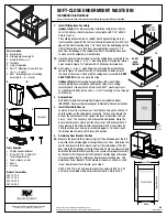
STEP 1
SUBFRAME INSTALLATION:
Change original belt guide
Install front supports
Install left rear support