


172 425 16 08-01
ELECTRIC EQUIPMENT
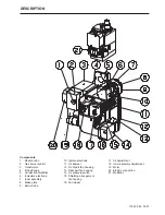
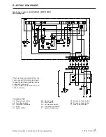
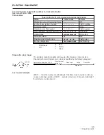
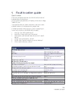
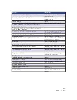
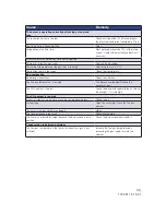
Component list
A1 Gas burner control
A2 Twin thermostat
B1 Ionization electrode
F1 Fuse
H1 Alarm, 230 V
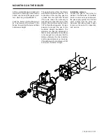
If there is no plug-in contact (X2) on the
boiler, connect to the contact enclosed.
In case the twin thermostat is in series
on incoming phase L1,
a loop between the terminals T1 and
T2 is necessary.
Mains connection in accordance with local regulations.
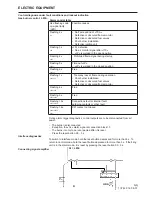
M1 Burner motor
S3 Main switch
S8 Air pressure switch
S9 Gas pressure switch
T1 Ignition transformer
X1 Plug-in contact, burner
X2 Plug-in contact, boiler
Y1 Gas solenoid valve
Gas burner control: LGB21/LMG21/LME11/LME21
Wiring diagram
1(5)
Summary of Contents for STG 146
Page 2: ......
Page 27: ......
Page 28: ...Enertech AB P O Box 309 SE 341 26 Ljungby www bentone se www bentone com...