


Adjustment of burner
The burner is from the factory pre-set
to an average value that must then
be adjusted to the boiler in question.
All burner adjustments must be made in
accordance with boiler manufacturers
instructions. These must include the
checking of flue gas temperatures,
average water temperature and CO
2
or O
2
concentration
General instructions
The installation of the gas burner must
be carried out in accordance with
current regulations and standards. The
installers of gas burners should therfore
be acquainted with all regulations and
ensure that the installation complies
with the requirements. The installation,
mounting and adjustment should be
made with the greatest care and only
the correct gas should be used.
Operating instructions
The operating instructions accompa-
nying the burner should be left in
a prominent position in the boiler
room.
Instructions
The user should be thoroughly
instructed in the function of the gas
burner and the whole installation. The
supplier must instruct the user.
Inspection and maintenance
Daily inspection is advisable.
Service
Service should only be carried out
by qualified personell. Replacement
parts should be of the same make and
approved by the same authorities as
the original. If the burner is converted
to fire another gas quality it must be
re-commissioned. If town gas is to be
fired the combustion head must be
converted and the gas train adjusted
to suit, (e.g.a larger gas armature or
a different spring in the governor may
be required).
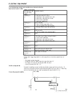
Start up
After the burner has been fitted to
the boiler and the electric connection,
the leakage control, the venting and
the electric function test have been
carried out, the burner will be ready
for start-up.
Hower, study the sections dealing
with adjustments of multi-bloc,
combustion air and combustion
head.
172 305 52 07-01
GENERAL INSTRUCTIONS
Open the ball valve and switch on the
main switch. If the burner starts the
actual adjustment can be made.
Air adjustment
On all burners the air adjustment can
be made with or without the cover
fitted. Final fine adjustment must be
made with the cover on.
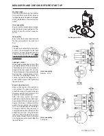
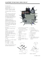
Adjustment of burner head
The burners are equipped with an
adjustment device changing the
position of the brake plate in the burner
head. This is used to adjust the corect
pressure drop over the combustion
device and thereby obtain a good
pulsation free combustion.
Which position to use depends on
input and overpressure in the boiler.
A general rule is that the lower capacity
the smaller the opening between brake
plate and combustion device.
Adjustment of brake plate
–
Turn by means of an allen key the
screw in the desired direction.
STG120/1, STG120/2, STG146/1
–
To reduce the opening: turn the
screw to the left.
–
To increase the opening: turn the
screw to the right.
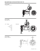
STG146/2
–
To reduce the opening: turn the
screw to the right.
–
To increase the opening: turn the
screw to the left.
The adjustment of the position of the
brake plate affects the air flow. It is
therefore always necessary to make a
fine adjustment of the air by means of
the adjustment device of the burner.
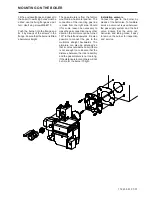
Control of burner head
To check the burner head, brake plate
and electrodes proceed as follows:
Remove the cover. Loosen the union
nut between inner assembly and multi-
bloc. Loosen the burner from the
flange and withdraw the burner from
the boiler. If it is necessary to remove
the burner tube, loosen the two allen
screws, turn and withdraw the burner
tube.
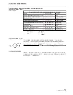
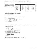
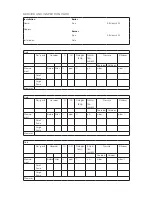
Commissioning of installation
Control of the combustion. The
combustion quality is checked by
means of a flue gas analysis device.
Adjust the burner to appr. 20% excess
air in accordance with the table. Check
the flue gas temperature. Calculate
the efficiency. Check also the actual
gas volume on the gas meter so that
the correct input is achieved.
Gas quality
CO
2
%
lambda 1,2
0
2
%
max CO
2
%
Natural gas
10,0
3,5
11,9
LPG
11,5
3,5
13,9
Summary of Contents for STG 146
Page 2: ......
Page 27: ......
Page 28: ...Enertech AB P O Box 309 SE 341 26 Ljungby www bentone se www bentone com...