BENTOFLEX ST120KA Installation And Maintenance  Instruction Download Page 10

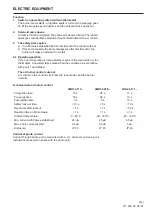
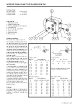
Function Danfoss BFP41

When the oil pump is started, oil is 

drawn from the suction connection 

(S) through the filter (H) to the suction 

side of the gear wheel (C).
The gear wheel then pumps oil to the 
pressure side and the oil is put under 
pressure.
The pressure is controlled and kept 
constant at the set value by the
regulating valve (P

1

) with the

diaphragm (D).
The regulating valve (P

1

) distributes 

the oil quantity supplied by the gear set 
(C) between the nozzle port (E) and 
the return side of the pump (R).
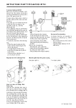
The oil quantity utilized is determined 
by the set pressure on the regulating 
valve (P

1

) and the size of the oil nozzle 

in the nozzle line.
The valve (P

1

) functions in the following  

way:

-  When the opening pressure has  

  been reached, the passage to the  
  return side opens.
-  The diaphragm and the spring  
  keep the pump pressure constant  
  at set value.
-  If the pump is overloaded, i.e. if  
  you try to get out more

  oil than the gear set can supply  
  under existing circum-stances, the  
  oil pressure falls below the set value 


  and the valve closes against the  
  return side (R) by means of the  
  diaphragm (D) and goes into starting  
 position.
This can be remedied by:
-  Reducing the pump pressure.
-  Reducing the oil quantity supplied  
  by using a smaller nozzle.
-  Using a pump with a larger capacity.

171 505 08  07-01

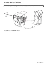
Replacement of cartridge filter

Burner with preheating

Consider that the oil quantity is 
reduced at preheating by 5-20% 
depending on.
-  Rise in temperature at the nozzle
-  Nozzle design

Capacity (high capacity - small  

 difference)

Mounting/dismounting return plug

How to remove cartridge filter

from plug

Unscrew  the  cartridge  filter  plug  in 

the cover by means of a 4 mm allen 

key and withdraw the cartridge filter. If 

necessary, put a screwdriver between 

the cartridge filter and the plug and 

turn the cartridge filter carefully until 

it comes off. Reject the cartridge filter 

and replace it by a new one. Press it 
on to the plug. Ensure that the

O-ring is not damaged. Then fit the 

new cartridge filter to the pump.

One pipe system

Two pipe system

R

S

E

NC

A

G

H

V

P

1

P

D

C

INSTRUCTIONS PUMP TYPE DANFOSS BFP41

Summary of Contents for ST120KA

Page 1: ...178 009 15 Installation and maintenance instruction BENTOFLEX ST120KA...

Page 2: ...ables 5 Nozzle assembly 6 Nozzle 7 Brake plate 8 Blast tube 9 Ignition electrodes 10 Connecting pipe 11 Air damper 12 Solenoid valve 13 Pump 14 Drive coupling 15 Indication air damper 16 Fan wheel 17...

Page 3: ...utput range and nozzles recommended The net calorific value of 11 86 kWh kg for light oil has been used Burner tube Length of burner tube Incl flange A Measure B Incl flange B Measure B Incl flange C...

Page 4: ...TECHNICAL DATA 171 215 76 07 01 Flange A 10 3 25 130 150 89 7 Flange C 10 125 90 4 Flange D 125 150 10 3 90 5 12 Flange B 89 5 12 136 150 Dimensions...

Page 5: ...ombustion free of soot By this procedure an optimum adjust ment is obtained If larger nozzles are used the preadjustment of the air volume must be increased Condensation in chimney A modern burner wor...

Page 6: ...MAINTENANCE OF OIL BURNER Warning Before doing any service switch off power at the main switch and cut off the oil supply 171 305 68 07 01 Service of burner head and nozzle assembly...

Page 7: ...R1 Photoresistor S3 Main switch T1 Ignition transformer Y1 Solenoid valve X1 Plug in contact burner X2 Plug in contact boiler Outer electrical connection Mains connection and fuses in accordance with...

Page 8: ...d by means of the main switch or the thermostat a new start takes place when the conditions in accordance with point 1 are fulfilled The oil burner control cuts out A red lamp in the control is lit Pr...

Page 9: ...mercial quality according to current standards On commis sioning with an empty tube system the oil pump should not be run without oil for more than 5 min a condition is that the pump is being lubricat...

Page 10: ...stances the oil pressure falls below the set value andthevalveclosesagainstthe returnside R bymeansofthe diaphragm D andgoesintostarting position This can be remedied by Reducing the pump pressure Red...

Page 11: ...93 9 71 115 99 10 24 121 104 10 73 127 109 3 00 9 98 118 102 10 59 126 108 11 16 132 114 11 71 139 119 3 50 11 65 138 119 12 35 146 126 13 03 154 133 13 66 162 139 4 00 13 31 158 136 14 12 167 144 14...

Page 12: ...1 21 133 114 11 67 138 119 12 11 144 123 12 53 148 128 3 00 12 23 145 125 12 73 151 130 13 21 157 135 13 67 162 139 3 50 14 27 169 145 14 85 176 151 15 42 183 157 15 95 189 163 4 00 16 31 193 166 16 9...

Page 13: ...magnetic valve Burner fails to start Lamp not lit Motor runs Burner runs to lockout Fuse has blown Appliance thermostat has not reset Appliance overheat device has operated Control relay or photocell...

Page 14: ...B20 B30 B40 B45 02119815004 B50 B60 B70 B80 040588622001 B55 040588622002 B65 Enertech AB declares under sole responsibility that the above mentioned product is in conformity with the following stand...

Reviews: