BENSON BSHH 055, Installation, Commissioning, Servicing
The BENSON BSHH 055 user manual is essential for the installation, commissioning, and servicing of your product. This comprehensive manual can be downloaded for free from manualshive.com, providing you with step-by-step instructions to ensure optimal performance and longevity. Download your manual today to maximize the benefits of your BENSON BSHH 055.
Share
Download


Reviews:
No comments
Related manuals for BSHH 055
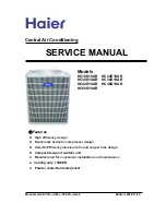
HC18D1VAR
Brand: Haier Pages: 32

HACI-MB 35E
Brand: Haier Pages: 40

HB2400VD1M20-P
Brand: Haier Pages: 16

HACI-RP 150
Brand: Haier Pages: 28

HC18D1VAR
Brand: Haier Pages: 17

HB2400VD1M20
Brand: Haier Pages: 18

HB2400VD2M20
Brand: Haier Pages: 16
HB3600VC1M25
Brand: Haier Pages: 15

HB2400VD1M20
Brand: Haier Pages: 16

WYS Series
Brand: Pioneer Pages: 16

DR024GHFE18HT2
Brand: Pioneer Pages: 16

TopMaster
Brand: flakt woods Pages: 28

BPRPGE14
Brand: Blue Summit Pages: 19

RM Series
Brand: AAON Pages: 24

4SCU14LB
Brand: Allied Pages: 43

Vision CAC 003 C
Brand: Daikin Pages: 86

RIS 1900VE EKO 3.0
Brand: Salda Pages: 32

X-CUBE X2
Brand: Trox Technik Pages: 89


