


15
GAMMA SELECTION
Gamma is what controls the overall brightness of an image.
Images which are not corrected properly can appear too white
or too dark, so controlling the gamma properly can have a huge
influence on the overall picture quality of your display.
The options are: {
NATIVE
} / {
2.2
} / {
2.4
} / {
S GAMMA
}.
NOISE REDUCTION
Adjust to remove the noise in the image. You can select a
suitable noise reduction level.
The options are: {
OFF
} / {
LOW
} / {
MIDDLE
} / {
HIGH
}.
NOTE: This item is functional for
HDMI
(Video mode),
Video
,
and
YPbPr
inputs only.
FILM MODE
Choose to turn on or off the film mode frame conversion
function.
•
{
AUTO
} - Enable the film mode frame conversion function
for movies and motion pictures. The display converts a
24 frames-per-second (24 fps) input signal format to DVD
video signal format. Once this function is enabled, it is
recommended that you set the {
SCAN CONVERSION
}
function to {
PROGRESSIVE
}.
•
{
OFF
} - Disable the film mode frame conversion function.
This mode is suitable for TV broadcasting and VCR signals.
PICTURE RESET
Reset all settings in the Picture menu to factory preset values.
4.2.2. SCREEN menu
PIP
1
2
3
SET
EXIT
MENU
:SEL
:NEXT
AUTO SETUP
AUTO ADJUST
H POSITION
V POSITION
CLOCK
CLOCK PHASE
ZOOM MODE
CUSTOM ZOOM
H RESOLUTION
V RESOLUTION
INPUT RESOLUTION
SCREEN RESET
SCREEN
:RETURN
:EXIT MENU
50
50
2200
66
1920
1080
FULL
OFF
AUTO SETUP
Use this function to let the display automatically optimize the
display of VGA input image.
NOTE: This item is functional for
VGA
input only.
AUTO ADJUST
Choose to let the display detect and display available signal
sources automatically.
•
{
ON
} - Set the display to display the image automatically
once a signal is connected.
•
{
OFF
} - Once a signal is connected, it can only be selected
manually.
H POSITION
Press the [ ] button to move the image to the right, or [ ] to
move the image to the left.
V POSITION
Press the [ ] button to move the image up, or [ ] to move the
image down.
CLOCK
Adjust the width of the image.
NOTE: This item is functional for
VGA
input only.
CLOCK PHASE
Adjust to improve the focus, clarity and stability of the image.
NOTE: This item is functional for
VGA
input only.
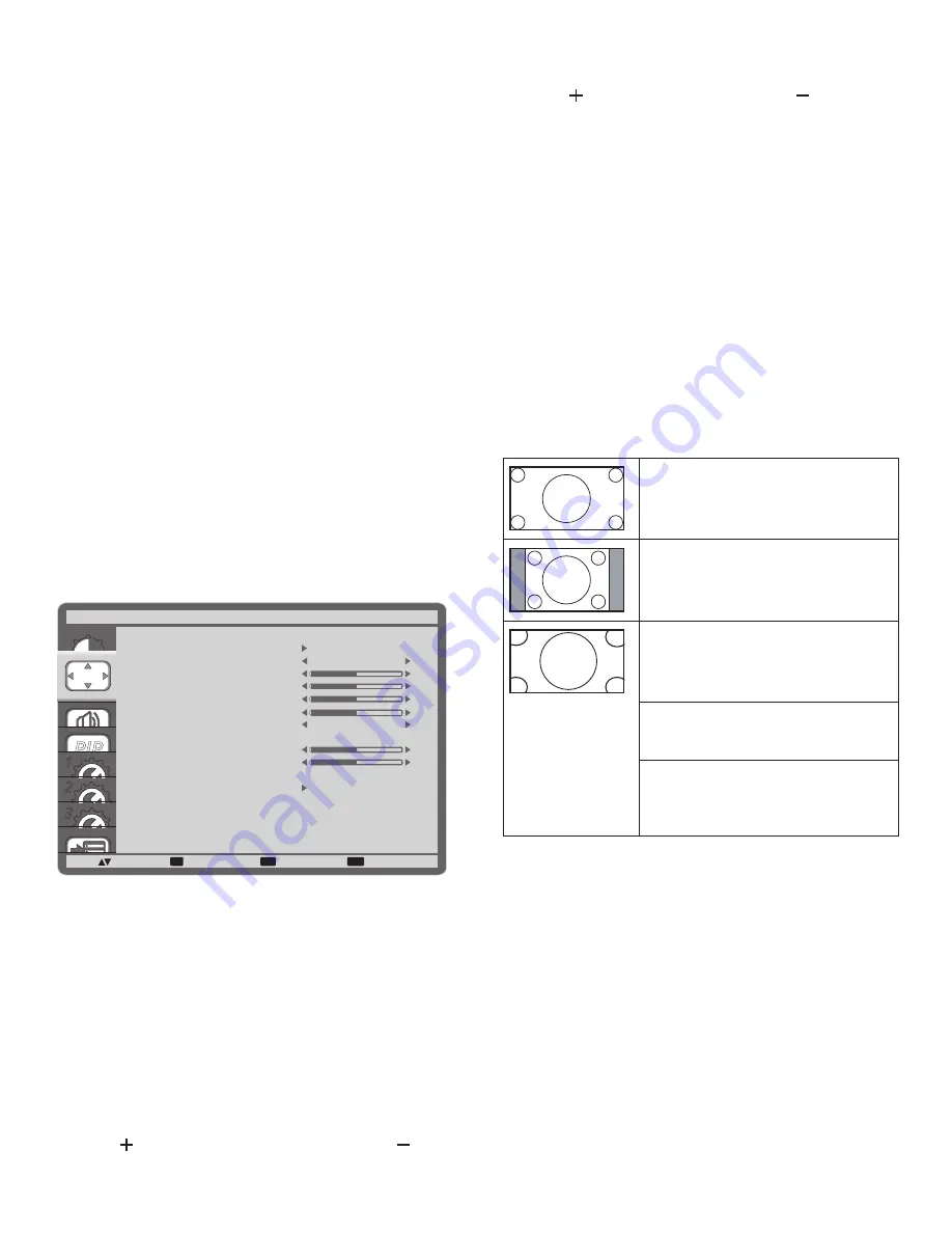
ZOOM MODE
The pictures you receive may be transmitted in 16:9 format
(wide screen) or 4:3 format (conventional screen). The 16:9
pictures sometimes have a black band at the top and bottom of
the screen (letterbox format).
This function allows you to optimize the picture display on
screen. The following zoom modes are available for:
•
PC mode: {
FULL
} / {
NORMAL
} / {
CUSTOM
} / {
REAL
}.
•
Video mode: {
FULL
} / {
NORMAL
} / {
DYNAMIC
} /
{
CUSTOM
} / {
REAL
}.
FULL
This mode restores the correct
proportions of pictures transmitted in
16:9 using the full screen display.
NORMAL
The picture is reproduced in 4:3 format
and a black band is displayed on either
side of the picture.
DYNAMIC
Fill the entire screen by stretching 4:3
pictures non-proportionally.
CUSTOM
Choose to apply the custom zoom
settings in the Custom Zoom submenu.
REAL
This mode displays the image pixel-
by-pixel on screen without scaling the
original image size.


