This document is described functions of AW-RP150 SYSTEM VERSION Ver 2.00-00-0.09. Please
see also the operating instructions of ROPs.
No.3
:
A ROP setting menu is added so that the selected camera at the AW-RP150
can be activated on the connected ROP.
-
AK-HRP1000/AK-HRP1005 ver.4.80-00-0.03 or higher
-
To use the ROP linkage function, PORT number of RP150 has to be same as one of ROP.
<
Setting ROP
>
【
MENU
】>
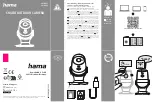
AW CONTROLLER LINK
Set up the PORT No. for RP150 to “RECEIVE PORT” and execute “INFO UPLOAD”.
Set “AW CONT LINK” to ON.
<
Setting RP150
>
【
MENU
】
SYSTEM
>
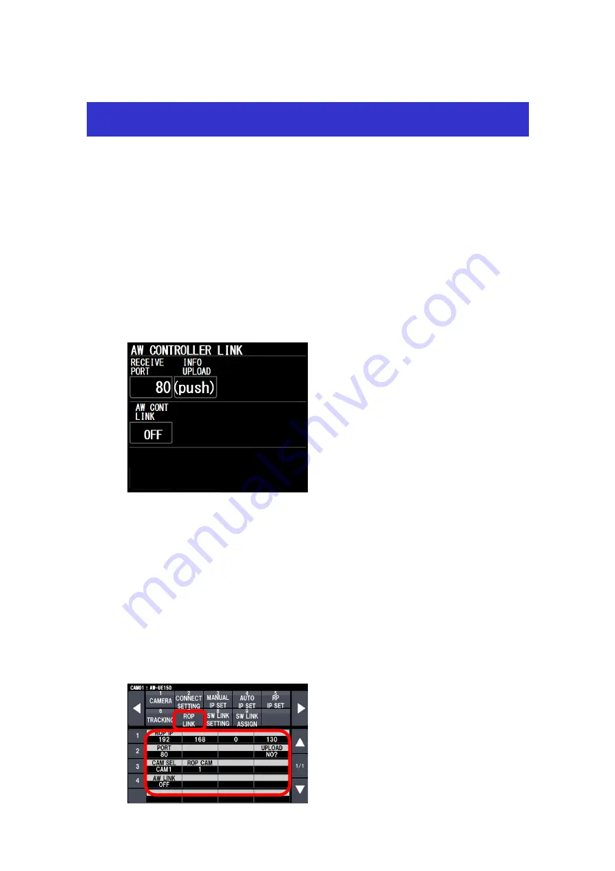
ROP LINK
Set up “ROP IP” and “PORT” for ROP. And execute “UPLOAD”.
Assign “CAMSEL” for RP150 and “ROP CAM” for ROP.
Target CAM No. can be set at “ROP CAM” against CAMSEL in RP150.
Initial setting : CAM1 –CAM99 is 1 – 99
CAM100 - CAM200 is NON
In case of no assigned CAMERA, please set it “NON”.
When “AW LINK” is turned on, RP150 starts to communicate to ROP.
Operating guide for AW-RP150 Ver2