background image

Getting Started with Your Display

5

Eng
lish

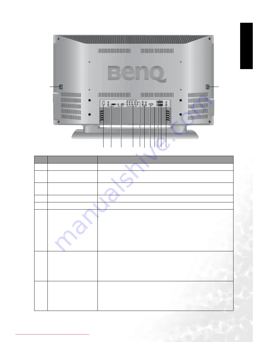
Main Unit (Rear View)

No.

Name

Description

1

AUDIO OUT (L/R)

Connect the audio input of an amplifier here.

2

AV2 (SCART connector) Allows you to connect to the SCART output terminal of your DVD 

player or other AV devices.

3

AV1 (SCART connector) Allows you to connect to the SCART output terminal of your DVD 

player or other AV devices.

4

TV/CATV Antenna

Connect your antenna to this input.

5

RS232

This terminal is for service purpose only.

6

AV3 (RCA connector)

• VIDEO (Composite (AV) signal input, RCA connector): Connect 

the Composite video output of your AV device here.

• AUDIO (Audio input, L/R): Connect the audio output of your AV 

device here. This input is used common to both AV and S-VIDEO 

input.

• S-VIDEO (S-VIDEO input): Connect the S-VIDEO output of your 

AV device here.

7

COMPONENT 2 

• Y C

B

/P

B

 C

R

/P

(Y C

B

/P

B

 C

R

/P

input): Connect the component image 

output of your AV devices or HDTV decoder here. The Y (green) 

connector can also be used as a second composite signal input.

• AUDIO (Audio input, L/R): Connect the audio output of your AV 

device here.

8

COMPONENT 1 

• Y C

B

/P

B

 C

R

/P

(Y C

B

/P

B

 C

R

/P

input): Connect the component image 

output of your AV devices or HDTV decoder here. The Y (green) 

connector can also be used as a second composite signal input.

• AUDIO (Audio input, L/R): Connect the audio output of your AV 

device here.

1

2

5

8

9

10

11

3

7 6

4

12

12

Downloaded From TV-Manual.com Manuals

Summary of Contents for DV3750

Page 1: ...Welcome English DV3750 LCD Display User s Manual Downloaded From TV Manual com Manuals...

Page 2: ...rity on safety however IMPROPER USE CAN RESULT IN POTENTIAL ELECTRICAL SHOCK OR FIRE HAZARD In order to prevent potential danger please observe the following instructions when installing operating and...

Page 3: ...13 Replacement parts In case the product needs replacement parts make sure that the service person uses replacement parts specified by the manufacturer or those with the same characteristics and perfo...

Page 4: ...surges and built up static charges For added protection for this television equipment during a lightning storm or when it is left unattended and unused for long periods of time unplug it from the wal...

Page 5: ...gnals Mini D SUB 9 Connecting DVI Signals 9 Connecting Audio Output Signals 10 Connecting the Power Cord 10 Initial Setup 11 Remote Control 12 Using the Remote Control 14 Batteries 14 Notes on Using B...

Page 6: ...igating the OSD Menu 19 Audio Menu 19 Picture Menu 21 Picture Mode Settings 22 Selecting a Picture Mode 22 Feature Menu 23 TV Menu 25 Performing Manual Installation 26 Editing Channels 26 Naming a Cha...

Page 7: ...crystal display please take the time to thoroughly read this manual particularly the sections on safety Functions and Features The DV3750 has many useful functions and features including 1920 x 1080 i...

Page 8: ...LCD Display If any item is missing or damaged contact an authorized dealer immediately Actual number and type of cables may vary with the location of purchase User s manual x1 Remote control x1 Power...

Page 9: ...the display is connected to a PC and the PC enters standby mode 2 Remote control sensor window Receives the signal from the remote control Do not put any objects in front of the window in order not to...

Page 10: ...the selection focus left and right or change settings 5 MENU button Press this button to display the OSD menu When the OSD menu is on press this button to exit the menu No Name Description 1 AV4 VIDEO...

Page 11: ...UDIO Audio input L R Connect the audio output of your AV device here This input is used common to both AV and S VIDEO input S VIDEO S VIDEO input Connect the S VIDEO output of your AV device here 7 CO...

Page 12: ...ctions are made picture or colour quality may be adversely affected Please ensure that all connectors are firmly seated Before connecting turn off the power to the external devices for safety 9 PC PC...

Page 13: ...t commonly used signal input However this type of input also provides a less optimal image quality Many video sources can only output Composite video signals for example VCRs and camcorders Other vide...

Page 14: ...PONENT Y CB PB CR PR terminals using a Component video cable 2 Connect the audio output of your AV equipment to the display s COMPONENT AUDIO L R input terminals using the AV cable or equivalent 1 Of...

Page 15: ...splay 4 The computer in the illustration is shown only for reference your equipment may vary 5 Additional equipment shown in the illustration is not provided 6 Do not set the computer s horizontal and...

Page 16: ...ou purchased the display This product must be operated only from the type of power source indicated on the marking label AC 100 240V 50 60 Hz If the display will not be used for a long period of time...

Page 17: ...ume buttons on the display to select your country and then press the Channel button on the display to go to the next step 5 Optional If Others is selected in Country press the Volume or Volume buttons...

Page 18: ...language broadcasts Lang 1 or Lang 2 can be selected When Teletext is displayed on the screen press this button to switch to a specific page 7 Picture mode Teletext page selection Press this button t...

Page 19: ...Teletext page selection Press these buttons to sequencially change channels When the TV is off press these buttons to turn it on and change channels When Teletext is displayed on the screen press thes...

Page 20: ...rong type of batteries may cause chemical leaks and or explosion Please note the following Always ensure that the batteries are inserted with the positive and negative terminals in the correct directi...

Page 21: ...Volume Adjusting the volume 1 Press the Volume button on your display or press the button on your remote control to increase volume The volume indicator will increase in length as volume rises 2 Press...

Page 22: ...ure PIP Picture by Picture PBP Function If your display is connected to an additional Video or PC source pressing the PIP PBP but ton allows you to display both images on the screen at once in PIP Pic...

Page 23: ...k Setting the backlight to Dark will reduce the image brightness and make the dark areas of the image darker thus maintaining a high contrast image in a dark environment Display Information Press the...

Page 24: ...On Screen Display OSD Menu 18 English On Screen Display OSD Menu OSD Structure Downloaded From TV Manual com Manuals...

Page 25: ...he submenu Press the MENU button on the remote control or the MENU button on your display to exit from the main menu For more information about the OSD menus please refer to the following pages Audio...

Page 26: ...l become unavailable if Audio Out is set to On Use the and buttons on the remote control or the Volume and Volume buttons on the display to change selection Off Auto Surround Select a surround sound e...

Page 27: ...int of the black and white part of the image Use the and buttons on the remote control or the Volume and Volume buttons on the display to change selec tion Panel Default Backlight color Warm Biased to...

Page 28: ...s the OK button to enter the submenu 3 Press the or button to select Advanced Picture Settings and press the OK button to enter the submenu 4 Press the or button to select Picture Mode and press the o...

Page 29: ...se the and buttons on the remote control or the Volume and Volume buttons on the display to change selection Left Right PIP PBP Display video and images simultaneously in either Picture In Pic ture or...

Page 30: ...gnal no change will occur Anamorphic Fill the entire screen with a 4 3 video signal Some deformations may be identified on the edge of the image When the input video source is 16 9 in ratio e g DVD si...

Page 31: ...nge selection English Fran ais Nederlands Deutsch Italiano Espa ol Country Select your country where the TV is installed Use the and buttons on the remote control or the Volume and Volume buttons on t...

Page 32: ...al 6 Optional If the SCART signal input is connected press the button to highlight Decode and then press the or buttons to select from the following options On Select this option if you are using a de...

Page 33: ...the or buttons to select from the following options Lock Lock selected channel Unlock Unlock selected channel 4 Press the MENU button to close the menus If a channel is locked it cannot be viewed if t...

Page 34: ...Function Operation Range DPMS Protect screen and enter power saver mode when no PC signal is detected Use the and buttons on the remote control or the Volume and Volume buttons on the display to chan...

Page 35: ...e is a loss of definition in the brightest areas of the image Reduce the contrast setting The DVD player is set for a high level output The AV video signal has not been terminated properly somewhere i...

Page 36: ...not disconnected Make sure the antenna is facing the right direction The picture is doubled or tripled Make sure the antenna is facing the right direction Picture ghosting is caused by reflections fro...

Page 37: ...fier 15W x 2 Signal inputs TV TV tuner Video S Video Composite video RCA Composite video SCART Component video Y PB PR Audio input PC DVI PC D sub DVI audio input PC audio Signal outputs SCART output...

Page 38: ...timal performance Dimensional Drawings Resolution Horizontal Freq khz Vertical Freq Hz Bandwidth Mhz Notes 720 400 31 47 70 08 28 32 DOS mode 640 480 31 47 60 00 25 18 DOS mode 640 480 37 50 75 00 31...

Reviews: