background image


Applicable Country & Regions: Global 


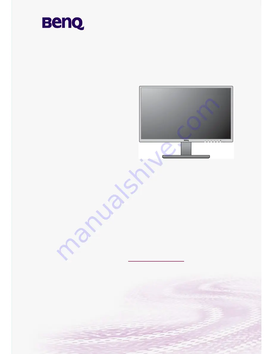
Service Manual for BenQ:


Version: 2

nd


Date: 6-22-2016 


Notice: 

For RO to input specific “Legal Requirement” in specific NS regarding to responsibility and 

liability statements. 

Please check BenQ

’s eSupport web site, http://esupport.benq.com, to ensure that you have 

the most recent version of this manual. 


Second Edition (June. 2016) 

©

 Copyright BenQ Corporation 2016. All Right Reserved.

GW2470H 


9H.LDMLA.TB* 

Applicable for All Regions


Summary of Contents for 9H.LDMLA.TB Series

Page 1: ...equirement in specific NS regarding to responsibility and liability statements Please check BenQ s eSupport web site http esupport benq com to ensure that you have the most recent version of this manu...

Page 2: ...4 Related service information 8 5 Product Overview 9 5 1 Monitor Specifications 9 5 2 Panel Inspection Specification 15 Level 1 Cosmetic Appearance Alignment Service 22 Visual Inspection Cleaning 22 S...

Page 3: ...Digital Micro mirror Device DRAM Dynamic RAM DVI Digital Visual Interface DVI D Digital Visual Interface digital DVI I Digital Visual Interface Integrated E EEPROM Electrically Erasable and Programma...

Page 4: ...olor signals for TV By mixing levels of R G and B all colors Y C are ROM Read Only Memory S SDA Data signal on I 2 C bus SDRAM Synchronous DRAM SW Sub Woofer Software T THD Total Harmonic Distortion V...

Page 5: ...any time When repairing the circuit board please follow the requirement of RoHS and refer to the circuit diagram and repairing process that attached in the Service Manual The method of firmware updat...

Page 6: ...ng any parts please confirming the RoHS requirement before replace them 2 2 Safety Warning and Notice Installation 1 Do not use your monitor under any of the following environmental conditions Extreme...

Page 7: ...c shock do not dissemble or repair the monitor 7 If a bad smell or an abnormal sound appears to come from the monitor contact your nearest BenQ service center for assistance immediately Cleaning 1 Ens...

Page 8: ...erating manual contains important information you require to start up and run your LED monitor This specification defines the requirements for the 24 MICROPROCESSOR based Multi mode supported high res...

Page 9: ...Panel maker AUO Video BenQ Senseye TM Technology Yes Picture mode Standard Low Blue Light Movie Game Photo s RGB ECO User Color Temperature Selection Normal 6500 K Reddish 5700 K Bluish 9300 K User M...

Page 10: ...re MHL NA Win 7 8 8 1 Yes Mac compatible NA SRGB Pro Yes HDMI Color Range Select Yes Component color Space select Yes Gamma Select 5 steps 2 2 3 0 Super resolution NA Smart focus NA Dynamic Power Savi...

Page 11: ...2015 06 26 BQC China CCC Y Printing Permissio n GB4943 GB9254 GB17625 1 Maker BENQ 2015 06 26 BQC China CCC Y Reports GB4943 GB9254 GB17625 1 Maker BENQ 2015 06 26 BQC China China Energy Label Y Certi...

Page 12: ...o Energy Label Y Reports Law for Sustainabl e Energy Apply by SI directly 2015 06 26 BQL Mexico NOM Y Certificate IEC 60950 1 2015 06 26 BQP Australia MEPS Y Certificate AN NZS 5815 2 2013 2015 06 26...

Page 13: ...2015 06 26 BQP Singapo re PSB Y Certificate IEC 60950 1 2015 06 26 BQP Singapo re PSB Y Evidence IEC 60950 1 2015 06 26 BQP Taiwan BSMI Y Authorizati on CNS1433 6 CNS1343 8 2015 06 26 BQP Taiwan BSMI...

Page 14: ...2015 06 26 Internati onal Internati onal Energy Star Y Reports ENERGY STAR Program Requirem ents for Displays 2015 06 26 Internati onal Internati onal RoHS BenQ GP Guideline Y Evidence 2011 65 E U SU...

Page 15: ...15 5 2 Panel Inspection Specification Inspection Standards for LCD Modules...

Page 16: ...16...

Page 17: ...17...

Page 18: ...18...

Page 19: ...19...

Page 20: ...20...

Page 21: ...21...

Page 22: ...binet are for ventilation They must not be blocked or covered Your monitor should never be placed near or over a radiator or heat source or in a built in installation unless proper ventilation is prov...

Page 23: ...cable to PC USB port will pop up a Hardware Wizard to help you install the USB driver if you use this ISP board first time You can install it successfully as the below instruction step by step Remark...

Page 24: ...24 Click Finish to complete the USB serial port driver installation...

Page 25: ...25 4 Update the Software 4 1 Double click to run the ISP tool 4 2 Connect to the monitor Click Connect If the tool communicate with monitor successfully the tool will detect the flash type of monitor...

Page 26: ...6 4 3 Load the F W you want to upgrade 4 4 Set the restore address 1 The monitor has DVI port you need to set restore address for HDCP key to avoid re program HDCP key HDCP KEY Start Address 07F000 4K...

Page 27: ...f connection during programming 4 7 Successful upgrade When upgrade successful there will be green Pass letter appearing 5 Check the FW version after upgrade 5 1 Verify the software version and turn o...

Page 28: ...28 3 Service Page and Verify the software version...

Page 29: ...ect signal source and power cable to monitor and DC off it 2 Press Enter key and Exit key as below figure at the same time and then Press Power Key to turn on the monitor When the screen lights releas...

Page 30: ...evice Type Error Method 1 Check the cables and ISP JIG are connected fluently 2 Click the Dis Con and click Connect again 3 AC off the monitor for a while and retry it 4 Change ISP JIG or cable 5 Chan...

Page 31: ...31...

Page 32: ...y 715GT034 B EDID writing SOP by VGA single port LPT cable male to male VGA cable 12V DC adapter TPV P N N A TPV P N 089G728 GAA DB TPV P N ADPC12416BEP ISP JIG 715GT034 B PC Monitor LPT port driver I...

Page 33: ...t PC after installation 4 Prepare the EDID written 4 1 Change the EDID files name as below rule VGA EDID WA dat HDMI EDID WH dat HDMI2 EDID WH2 dat 4 2 Copy these files to one folder named as BENQ GW2...

Page 34: ...34 5 Run the ISP tool 5 1 Double click the icon to open the tool 5 2 Select the EDID folder...

Page 35: ...35 5 3 Load EDID successful 5 4 Tick the Only connect VGA and Write SN then click Debug Imformayion...

Page 36: ...g When The green PASS appear the process is finished 6 Troubleshooting 6 1 Can t write 1 AC on the monitor and turn on it Restart the monitor 2 Take apart the monitor and connect the 7pin of EEPROM to...

Page 37: ...37 Adjustment Alignment Procedure The Control Panel...

Page 38: ...2 The hot key menu is displayed The left three controls are custom keys and are designated for particular functions 3 Select Menu to access the main menu 4 In the main menu follow the icons next to t...

Page 39: ...is the hot key for Brightness Enters sub menus Selects menu items Menu Activates the main menu Returns to the previous menu Exit Exits OSD menu OSD On Screen Display The hot keys only operate while th...

Page 40: ...ar on the menu 1 Select Menu from the hot key menu 2 Use or to select Display 3 Select to go to a sub menu and then use or to select a menu item 4 Use or to make adjustments or use to make selection 5...

Page 41: ...ition of the screen image 0 to 100 Pixel Clock Adjusts the pixel clock frequency timing to synchronize with the analog input video signal Not applicable to a digital input signal 0 to 100 Phase Adjust...

Page 42: ...appear on the menu 1 Select Menu from the hot key menu 2 Use or to select Picture 3 Select to go to a sub menu and then use or to select a menu item 4 Use or to make adjustments or use to make selecti...

Page 43: ...Green and Blue primary colors can be altered to change the color tint of the image Go to the succeeding R red G green and B blue menus to change the settings Decreasing one or more of the colors will...

Page 44: ...2 Use or to select Picture Advanced 3 Select to go to a sub menu and then use or to select a menu item 4 Use or to make adjustments or use to make selection 5 To return to the previous menu select 6 T...

Page 45: ...rd mode while the right window presents the images under the specified mode ON OFF Dynamic Contrast The function is to automatically detect the distribution of an input visual signal and then to creat...

Page 46: ...put source is HDMI color format is not selectable In other words Color Format is automatically set depending on the input video source RGB For D Sub VGA input source from PC For DVI input source YUV F...

Page 47: ...ons will disappear For models without certain functions their settings and related items will not appear on the menu 1 Select Menu from the hot key menu 2 Use or to select Audio 3 Select to go to a su...

Page 48: ...isabled and the corresponding OSD icons will disappear For models without certain functions their settings and related items will not appear on the menu 1 Select Menu from the hot key menu 2 Use or to...

Page 49: ...he OSD menu 5Sec Time 10Sec 15Sec 20Sec 25Sec 30Sec OSD Lock Prevents all the monitor settings from being accidentally changed When this function is activated the OSD controls and hotkey operations wi...

Page 50: ...n the input auto select loop Otherwise HDMI can only be selected by input select or by hot key ON OFF Auto Power Off Sets the time to power off the monitor automatically in power saving mode OFF 10min...

Page 51: ...25 18 31 47 70 09 FS FS FS FS FS O FS FS FS FS FS FS FS 640x 350 31 50 37 86 85 08 NP NP NP NP NP O NP NP NP NP NP NP NP 640x 400 25 18 31 47 70 09 FS FS FS FS FS O FS FS FS FS FS FS FS 640x 400 31 5...

Page 52: ...NP NP NP NP NP NP NP 848x 480 31 50 29 83 59 66 NP NP NP NP NP NP NP NP NP NP NP NP NP 848x 480 37 52 35 00 70 00 NP NP NP NP NP O NP NP NP NP NP NP NP 848x 480 39 25 36 07 72 00 NP NP NP NP NP O NP N...

Page 53: ...NP NP NP NP 1152 x900 105 59 71 73 76 07 P P P P P P P P P P P P P 1280 x720 74 25 45 00 59 94 CVT 7 P P P P P P P P P P P P P 1280 x720 74 50 44 77 59 86 P P P P P FS P P P P P P P 1280 x720 95 75 5...

Page 54: ...4 90 74 40 70 00 P FS NP NP NP O NP NP NP NP NP NP NP 1280 x102 4 134 60 77 90 72 00 DMT 1 2 P FS P P P FS P P P P P P P 1280 x102 4 135 00 79 98 75 02 FS FS NP NP NP O NP NP NP NP NP NP NP 1280 x102...

Page 55: ...59 910 CVT 1 0 NP NP NP NP NP NP NP NP NP NP NP NP NP 1600 x100 0 132 25 62 14 59 87 O O O FS NP O NP NP NP NP NP NP NP 1600 x100 0 169 25 78 356 74 83 CVT 2 FS FS FS FS NP NP NP NP NP NP NP NP NP 16...

Page 56: ...O O NP NP 1792 X134 4 257 75 105 29 0 75 00 CVT2 58M3 O O O O O O O O O O O NP NP 1856 X139 2 217 25 86 485 59 934 CVT2 58M3 O O O O O O O O O O O NP NP 1856 X139 2 277 5 109 74 918 CVT2 59M4 O O O O...

Page 57: ...9 95 O O O O FS FS FS FS P P FS P P 1920 X120 0 193 25 74 56 59 89 O O O O O O O O FS O O NP NP 1920 X120 0 245 25 94 04 74 93 CVT2 76M3 R O O O O FS FS FS FS FS FS FS NP NP 1920 X144 0 R 184 75 88 82...

Page 58: ...560 x160 0 R 268 5 98 713 59 972 4 10M A O O O O O O O O O O O O O 2560 x160 0 348 5 99 4 59 9 DMT 4 E O O O O O O O O O O O 2560 x160 0 443 25 125 35 4 74 972 DMT 4 F O O O O O O O O O O O 2560 x160...

Page 59: ...640 160 525 480 45 2 3 Y Prog 27 027 31 500 60 000 858 720 138 525 480 45 4 Y Prog 74 250 45 000 60 000 1650 1280 370 750 720 30 5 Y Int 74 250 33 750 60 000 2200 1920 280 1125 1080 23 6 7 NA Int 74 2...

Page 60: ...as normal OSD define 6 The timer can only reset at the service mode by Timer Reset Timer Reset moves to SI factory Area And needs to have a warning message to double confirm the reset function The ti...

Page 61: ...t notice Please go to http cs tpv com cn hello1 asp for the latest information Item Description Qty Unit 1 BEZEL 1 PCS 2 SPONGE 1 PCS 4 KEY BOARD 1 PCS 5 LENS 1 PCS 6 KEY 1 PCS 7 LCD PANEL 1 PCS 8 INS...

Page 62: ...OWER BOARD MAINFRAME 4 PCS 13 0M1G 930 6120 MAIN BOARD MAINFRAME 2 PCS 18 0M1G3030 6 47 CR3 REAR_COVER HINGE 2 PCS 20 0Q1G2030 6120 STAND HINGE BASE BKT_BASE 8 PCS 26 Q01G700100A004 HINGE BASE BKT_BAS...

Page 63: ...63 Six Angles View...

Page 64: ...Product Disassembly Assembly Disassembly 1 Remove the stand base Remove the base Remove the screw to remove the base Remove the stand Press the hole pull at the stand strongly at the same time The ho...

Page 65: ...65 2 Remove the rear cover Remove the screws in red to remove the rear cover Pull apart bezel rear cover Note Be careful the BEZEL CLIP is easy to break Bellow picture for reference...

Page 66: ...een CLIPS It s suggested to separate bezel and rear cover from the gaps 3 Remove the main frame from the panel Remove the black rubberized fabric and aluminum foil Note When you assembled the LCD you...

Page 67: ...e to remove the mainframe Note When you assembled the LCD you must tidy the wire as follow picture 4 Remove the boards from the main frame Remove Mylar from power board Remove the main board The mainf...

Page 68: ...rom the main board 5 Remove the panel Note Be course the panel is easy to broken when we remove the panel we should hold the iron on the panel edge use two hands at the same time and should avoid touc...

Page 69: ...69 6 The bezel and Key board...

Page 70: ...70 Assembly 1 Assemble key board to bezel 2 Assemble the panel into bezel...

Page 71: ...main frame Connect main board and power board assemble the wire the power board to main board and FFC cables the Wire from main board will connect to panel Lock the main board and power board on the...

Page 72: ...72 4 Assemble the main frame Connect key board and main board panel and power board panel and main board Note When you assembled the LCD you must tidy the wire as follow picture The mainframe...

Page 73: ...73 5 Assemble the rear cover Assemble the rear cover and lock the screws 6 Assemble the stand base Push the stand as follow picture Lock the screw to assemble the base...

Page 74: ...olor Clean the LCD screen Cycle power on off These pixels are permanently on or off and that is a natural defect occurs in LED technology The image has a faulty coloration It has a yellow blue or pink...

Page 75: ...storted Images from different input sources may appear distorted or stretched on the monitor running at its native resolution To have the optimal display performance of each type of input sources you...

Page 76: ...Check Power On Off is On Re plug the power cable Replace main board and check connections Check the LED indicates is OK Check the AC power er Replace the power board OK NG OK NG NG Turn on the Power...

Page 77: ...LLOW Press the power button is OK Check the LVDS FFC cable or panel The end NG OK OK NG Replace the main board Replace the power board Replace the LVDS FFC cable or panel The end Replace the key board...

Page 78: ...mode Set to the optimal frequency select the recommended frequency Pull out signal cable and check Self Test Feature Check is ok Check the signal cable and the PC Readjust the phase and pixel clock i...

Page 79: ...shift Replace the signal cable Pull out the signal cable and check the screen color display is normal The end Replace the signal cable or PC Reset the factory mode In the user mode set the color setti...

Page 80: ...0601200AXL M4 6 POWER BOARD MAINFRAME 1 6 1kgf cm 0D1G1030 6120 D3 6 MAIN POWER BOARD MAINFRAME 4 6 1kgf cm 0M1G 930 6120 3 6 MAIN BOARD MAINFRAME 2 6 1kgf cm 0M1G3030 6 47 CR3 M3 6 REAR_COVER HINGE 2...

Reviews: