background image

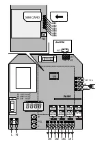
RADIO RECEIVER MODULE 

In this second part, the four channel radio receiver functions are described such as wire connections, output 
configuration, memorising of transmitters, etc..

SPECIFICATIONS 

- Four output, independent and freely configurable channels
- Rolling code radio receiver - 433.92MHz frequency
- Programming through built-in LCD display
- Standard memory for 512 transmitters. It can be replaced with MEM2048 module for 2048 transmitters
- Versions with 230VAC, 115VAC or 24VAC/CC power supply are available.
- Input  for 12VDC emergency battery, with automatic charge.

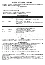
INPUT/OUTPUT FUNCTIONS

Input,  No. 

Function

Description

1-2

Power supply 

Input,  230Vac 50Hz (1-Phase/2-Neutral) in the 230V version
Input,  115Vac 60Hz  (1-Phase/2-Neutral) in the 115V version
Input,  24 Vac/dc (1+ /2 -) in the 24V version

3-4

Channel 1

Output,  channel 1. 230 Vac max 5A.
Normally  Open  (N.O.)  Contact,  switchable  in  Normally  Closed  (N.C.) 
through jumper 1.  

5-6

Channel 2

Output,  channel 2. 230 Vac max 5A.
N.O. Contact, switchable in N.C. through jumper 2.  

7-8

Channel 3

Output,  channel 3. 230 Vac max 5A.
N.O. Contact switchable in N.C. through jumper 3.  

9-10

Channel 4

Output,  channel 4. 230 Vac max 5A.
N.O. Contact, switchable in N.C. through jumper 4.  

11-12

Antenna

Antenna connection of the built-in radio module 
(11-screen/12-signal). 

13-14

Battery 

Input for emergency battery, 12Vdc (13:- / 14:+). 
It allows the operation of the receiver in case of power failure of the 
mains, During the mains operation the battery is recharged.
Recharge time, about 15 hours for a battery 12V/1,2Ah.

Note: 

The U2 memory can contain 512 rolling-code, 433.92MHz, transmitters maximum. If necessary, it can be 
replaced with item MEM2048 which can contain up to  2048 different codes.
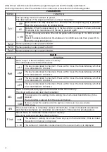
PROGRAMMING 

The programming of the various functions of the control unit is carried out by using the LCD display in the 
receiver and presetting the desired values in the programming menus described hereunder. 
1 - Press the <PG> key,  the display shows the first Parameters Menu “PAR”. 
2 - By using the keys <+> or <->, select the desired Menu  (PAR>>LOG>>RADIO>>....).
3 - Press the <PG> key, the display shows the first function available on the Menu.
4 - By using the keys <+> or <->, select the function to be modified.
5 - Press the <PG> key,  the currently preset value for the selected function is displayed.
6 - By using the <+> or <-> keys, select the value to be assigned to the function.
7 - Press the <PG> key, “PRG”  is displayed which means the programming has been successful.

Note: 

You can return to the upper menu without making changes if you press the <+> and <->  keys simultaneously 
in a Function Menu.
If you press the <+> and <->  keys simultaneously when the display is switched off, the card software version 
is shown. Press PG to select the desired value. OK is shown to confirm a successful programming.
If either the <+> key or the <-> key are kept pressed, the increase/reduction of numeric values is accelerated 
in the Time Menu.

12

13

Summary of Contents for CALL

Page 1: ...L8542447 06 2009 rev 3 ENG CALL UNIONE NAZIONALE COSTRUTTORI AUTOMATISMI PER CANCELLI PORTE SERRANDE ED AFFINI ...

Page 2: ...AT N CH1 PG CH2 CH3 CH4 L ANT SHIELD ANT BATT 12Vdc U2 RADIO J4 CH4 N O CH4 N C J3 CH3 N O CH3 N C J2 CH2 N O CH2 N C J1 CH1 N O CH1 N C ADV N C 1 2 3 4 5 6 7 8 9 10 11 12 13 14 F1 T315mA LED1 LED2 LED3 LED4 LED5 LED6 PB1 ALARM 1 2 3 4 5 SIM CARD ...

Page 3: ... mode is Open Access the system is ready for use Check that the SIM that is to be used for the CALL system is activated take note of the telephone number of the SIM itself The vocal calls and the SMS controls can be sent also from fixed telephones WARNINGS The customized password modpsw and in general when commands are typed in it is important not to leave any spaces unintentionally The system in ...

Page 4: ...ot provide for the storage in memory of the telephone numbers in the CALL memory Any telephone may therefore activate the channels through a call or an activation SMS mes sage thus exceeding the preset 200 number limit of the standard mode HOW TO CONNECT SWITCH ON AND INITIALIZE THE SYSTEM Introduce a SIM card in the special seat in the device There are no limits to the network operator However th...

Page 5: ...tatus is as follows LED 1 flashing every 2 seconds LED 2 and LED 3 continuous flashing LED 4 from 1 to 5 flashes to show reception level LED 5 switched off it switches on if an SMS is received LED 6 switched on with fixed light ACCESS PASSWORD All programming controls provide for an access password For safety reasons the first operation to be carried out is to change password Send an SMS message w...

Page 6: ...will be activated or send ch2 ch3 ch4 according to the channel to be activated As described hereunder the text of the message intended to activate the channels can be modified Note if you wish to receive an acknowledgement text message by the CALL device the message must be ch1 The reply will be COMANDO ESEGUITO CORRETTAMENTE COMMAND OK PROGRAMMING Programming is performed by sending the control s...

Page 7: ...tivates channel 1 2 the phone call activates channel 2 3 the phone call activates channel 3 4 the phone call activates channel 4 Digit 2 activation of channel 1 by SMS 0 denied access channel 1 cannot be activated through SMS 1 channel 1 can be activated through the sending of SMS1 Digit 3 activation of channel 2 by SMS 0 the phone call activates channel channel 2 cannot be activated through SMS 1...

Page 8: ...ers stored in memory maximum phone numbers storable in memory STATUS REQUEST OF PRESETTING AND PERMITTED ACCESSES OF A NUMBER This command allows to know presetting presetting of alarm and channel to be activated by phone call and permitted accesses channels which can be activated by SMS regarding one specific number stored in memory numstatus 123456 3391234567 where numstatus command string 12345...

Page 9: ...h3 and Ch4 words corresponding to SMS1 SMS2 SMS3 SMS4 respectively If a reply should be sent by the device the command shall be setcmdmsg 123456 1 GATE The reply will be COMMAND MESSAGE SET ADD TRANSMITTER CODE IN THE RECEIVER CONNECTED TO MODULE This command permits to add a transmitter code to the receiver memory without necessarily gain access to the control unit the serial number of the transm...

Page 10: ...6 02D762D where testtx command string 123456 access password 02D762D string of 7 hexadecimal digits 0 F representing the SN of the TX to request the status The reply will be one of the following TRANSMITTER ENABLED TRANSMITTER DISABLED TRANSMITTER NOT PRESENT ACTIVATION OF THE TRANSMITTER ENTER BLOCKTHROUGH RECEIVER This command permits to block the access to the radio menu functions of the receiv...

Page 11: ...ror messages through SMS COMMAND MESSAGE NOT SET Check the syntax of the command string NO PASSWORD FOUND Check the syntax of the password configuration command COMMAND EXECUTION ERROR The command was not executed SYNTAX COMMAND ERROR The command is correct but the parameter syntax is incorrect PASSWORD ERROR Check password ERROR UNKNOWN General error ERROR MEMORY FULL Receiving memory is full No ...

Page 12: ...d hereunder addalarmnum 123456 NN3391234567 NN3391234568 NN3391234569 etc where addalarmnum command string 123456 access password NN3391234567 telephone number with international code if more than one number must be typed in with one single message it is suficient to separate the numbers with the number NN3391234567 and following will be called if an alarm occurs In this case the international cod...

Page 13: ... 13 14 It allows the operation of the receiver in case of power failure of the mains During the mains operation the battery is recharged Recharge time about 15 hours for a battery 12V 1 2Ah Note The U2 memory can contain 512 rolling code 433 92MHz transmitters maximum If necessary it can be replaced with item MEM2048 which can contain up to 2048 different codes PROGRAMMING The programming of the v...

Page 14: ...Press within 5 sec the transmitter key which is to be associated to channel 1 CH2 The key is associated to channel 2 Press within 5 sec the transmitter key which is to be associated to channel 2 CH3 The key is associated to channel 3 Press within 5 sec the transmitter key which is to be associated to channel 3 CH4 The key is associated to channel 4 Press within 5 sec the transmitter key which is t...

Page 15: ...15 ...

Page 16: ... ...

Reviews: