


Fokker
EIII
Page
22
Copyright©
2007
M.K.
Bengtson
All
Rights
Reserved
Rev
07/11
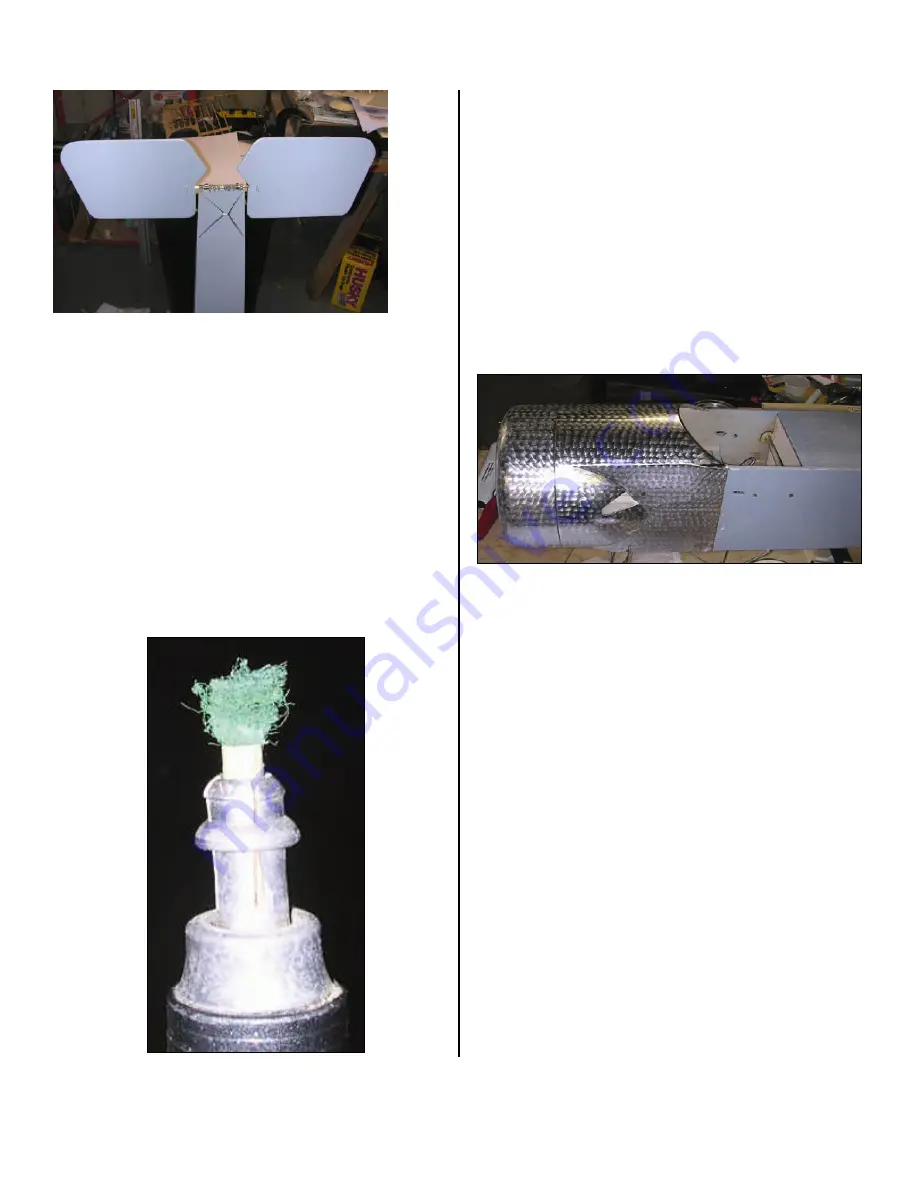
The
front
end
of
the
EIII
is
covered
with
aluminum
sheet
(cockpit
forward
and
cowl).
To
replicate
this
I
covered
these
sections
with
some
chrome
Ultracoat.
It
went
on
well
but
I
learned
that
when
covering
solid
surfaces
with
this
material
you
have
to
be
very
careful
with
the
temperature.
If
it
gets
to
hot
it
seems
to
dull
very
quickly.
So
a
bit
of
experimenting
found
a
good
temp.
The
fuselage
sections
were
covered
in
individual
pieces
to
pattern
after
the
full
scale
ship.
I
wanted
to
cover
the
cowl
in
two
pieces,
one
left
side
and
one
right
side
but
the
radius
on
the
front
edge
of
the
cowl
was
too
difficult
to
cover
without
getting
a
lot
of
wrinkles
ironed
in
so
I
ripped
it
off
and
covered
the
cowl
with
about
six
smaller
pieces
that
were
easier
to
handle.
>>
One
of
the
features
of
the
Fokker
Eindeckers
is
the
distinctive
swirl
pattern
on
the
metal
covered
areas.
Like
the
Spirit
of
St
Louis,
if
it
is
not
there
it
just
does
not
look
right.
One
of
the
previous
posters
suggested
using
a
piece
of
a
Scotch
Brite
scouring
pad
to
impart
the
swirls.
I
have
an
old
electric
drafting
eraser
that
I
chucked
a
length
of
1/4
ʺ
diameter
wood
dowel
in
and
glued
a
small
circle
of
the
Scotch
Brite
pad
to
it
with
a
drop
of
CA.
I
made
up
a
small
test
section
of
Chrome
Ultracote
ironed
on
to
a
scrap
of
wood
and
went
to
town.
Came
out
well
so
I
started
on
the
EIII.
Took
about
30
minutes
to
do
all
of
the
chrome.
I
had
to
change
the
pad
piece
a
number
of
times
but
I
think
the
effect
came
out
well.
Next
is
the
attachment
of
the
rudder
pivot
tube
support
piece
to
the
elevator
pivot
support
tube.
The
design
calls
for
a
short
section
of
brass
tubing
that
fits
into
the
slot
left
in
the
rudder
when
it
was
originally
built
(See
post
#31
on
page
3).
This
piece
of
brass
tubing
is
to
be
bound
to
the
elevator
pivot
support
tube
using
some
Kevlar
thread
and
epoxy.
I
decided
to
cut
the
section
of
tube
and
then
silver
solder
it
to
the
elevator
tube
as
this
would
make
for
a
neater
installation.
The
design
is
fine
and
in
fact
is
probably
somewhat
easier
to
do,
however,
one
never
builds
a
plane
exactly
according
to
the
design
does
one??!!!!!
I
used
3/16
ʺ
diameter
tubing
on
the
rudder
or
the
pivot
support
tubes
as
the
rudder
balsa
pieces
were
also
3/16
ʺ
thick.
I
thus
cut
a
short
section
of
3/16
ʺ
brass
tube
to
fit
the
gap
minus
about
10
thousands
or
so
to
allow
for
a
free
fit.
I
then
used
a
small
length
of
5/32
ʺ
brass
tube
as
the
pivot
to
check
the
fit,
smoothness
of
rotation
on
the
pivot
etc.
When
done,
I
then
used
a
piece
of
sandpaper
to
thoroughly
clean
the
tube
piece
and
the
area
of
the
elevator
pivot
support
tube
where
it
would
be
attached.
I


