


Fokker
EIII
Page
13
Copyright©
2007
M.K.
Bengtson
All
Rights
Reserved
Rev
07/11
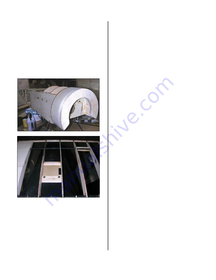
the
front
of
cowl
piece
C2
to
form
the
front
of
the
cowl.
When
this
is
done,
the
front
edge
is
rounded
over
fairly
severely
to
get
the
proper
shape.
I
have
not
yet
started
to
round
over
the
cowl
front.
The
cowl
is
attached
to
the
firewall
using
two
4
‐
40
screws
and
blind
nuts.
The
holes
in
the
firewall
are
the
correct
diameter
for
the
4
‐
40
blind
nuts
so
there
are
installed
there
and
glued
in
place.
I
used
two
4
‐
40
x
3/8
ʺ
long
socket
head
cap
screws
to
hold
the
cowl
in
place.
If
you
look
in
the
photo,
you
can
see
one
of
the
cap
screws.
AILERONS
The
full
size
EIII
used
wing
warping
for
roll
control.
Since
this
is
a
semi
scale
model
and
rigging
up
a
functional
wing
warping
system
would
be
a
bit
of
a
job,
this
particular
bird
was
designed
with
full
span
strip
ailerons.
When
hinged
from
the
top
and
the
hinge
gap
covered
they
should
not
be
too
noticeable
and
it
allows
the
plane
to
retain
the
scale
dihedral
instead
of
the
5
degrees
or
so
per
panel
that
a
rudder/elevator
design
would
require.
The
plan
calls
for
a
Hitec
HS
‐
55
in
each
panel
to
drive
the
aileron
in
each
wing.
I
had
a
couple
of
HS
‐
81
ʹ
s
laying
around
looking
for
an
application
so
I
decided
to
use
them.
As
the
HS
‐
81
ʹ
s
are
a
bit
bigger
I
moved
the
servo
location
back
away
from
the
TE
a
bit
more
to
allow
the
servo
to
fit
easily
within
the
wing
structure.
Two
laser
cut
servo
hatches
from
1/32
ʺ
ply
are
provided
in
the
kit.
As
I
have
a
nasty
habit
of
breaking
these,
I
made
two
new
ones
from
1/16
ʺ
ply.
I
located
the
back
end
of
the
hatch
5
ʺ
from
the
trailing
edge
and
glued
in
a
piece
of
1/16
ʺ
x
3/8
ʺ
balsa
flush
with
the
rib
bottom.
This
will
form
part
of
the
hatch
hold
down
and
also
give
the
covering
something
to
grab
on
to.
I
then
placed
the
hatch
cover
in
place
and
glued
another
piece
of
1/16
ʺ
x
3/8
ʺ
balsa
at
the
other
end
flush
with
the
rib
bottom.
I
then
glued
a
piece
of
1/16
ʺ
x
3/8
ʺ
balsa
to
the
back
end
of
the
hatch
cover
to
form
a
tongue.
This
will
slip
into
a
slot
at
the
back
3/8
ʺ
balsa
piece
to
retain
the
hatch
cover.
The
front
end
gets
held
in
place
with
some
2
‐
56
screws
and
blind
nuts.
I
cut
a
piece
of
1/8
ʺ
lite
ply
9/16
ʺ
wide
and
glued
it
to
the
inside
face
of
the
forward
3/8
ʺ
balsa
piece
allowing
about
3/8
ʺ
or
so
to
extend
into
the
servo
area.
This
forms
the
piece
that
the
blind
nuts
will
attach
to.
I
then
laid
the
hatch
cover
in
place
and
at
the
trailing
edge
end
I
glued
a
piece
of
1/8
ʺ
sq
spruce
on
top
of
the
balsa
tongue
(glue
to
the
ribs
only).
This
forms
the
slot
that
the
tongue
slips
into.
I
then
drilled
two
holes
about
3/16
ʺ
in
from
the
forward
edge
and
about
1/4
ʺ
in
from
the
sides
through
the
servo
hatch
cover
and
the
underlying
1/8
ʺ
lite
ply
plate.
These
are
the
located
for
the
hold
down
screws.
I
then
enlarged
the
holes
in
the
lite
ply
plate
and
installed
2
‐
56
blind
nuts.
The
hatch
cover
can
now
have
the
rear
end
tongue
slipped
into
the
slot
and
the
hatch
held
down
by
the
two
2
‐
56
screws.
The
servo
is
held
in
place
by
two
pieces
of
3/8
ʺ
sq
basswood
each
about
5/16
ʺ
long.
The
servo
location
is
marked,
the
two
bas
pieces
glued
in
place
and
some
triangle
stock
added
to
help
reinforce
the
pieces.
The
mounting
holes
are
then
drilled
and
the
servo
is
screwed
in
place
using
the
2
‐
56
servo
mounting
screws
that
Micro
fasteners
sells.
These
are
the
2
‐
56
Socket
Head
screws
with
the
integral
washer.
These
are
great
items
by
the
by.


