


Fokker
EIII
Page
18
Copyright©
2007
M.K.
Bengtson
All
Rights
Reserved
Rev
07/11
tubes.
The
guide
tubes
are
lengths
of
1/32
ʺ
ID
plastic
tubing.
They
are
cut
to
length
and
glued
into
the
balsa
supports
and
then
cut
flush
with
the
balsa
supports
and
sanded
smooth.
The
balsa
guide
tube
support
are
a
tad
flimsy
so
I
added
a
piece
of
scrap
1/8
ʺ
x
1/4
ʺ
balsa
under
the
balsa
guide
tube
support
pieces
to
stiffen
things
up.
The
ends
in
the
fuselage
are
supported
by
a
piece
of
1/8
ʺ
x
1/4
ʺ
balsa
glued
across
the
fuselage.
In
order
to
get
the
proper
location
and
spacing
on
the
guide
tubes
at
this
area,
I
installed
the
rudder
servo
and
ran
lengths
of
spider
wire
thru
the
tubes
to
the
servo
arm.
I
was
able
to
then
get
the
correct
geometry
and
spacing
of
the
guide
tubes.
I
then
located
the
holes
on
the
support
piece,
drilled
the
holes
using
a
bit
held
in
my
hand
and
glued
the
tubes
in
place.
The
elevator
guide
tubes
are
done
in
a
similar
manner.
I
made
one
change
here
from
the
original
design.
On
the
full
size
EIII
the
elevator
cable
horns
are
located
in
each
elevator
half
a
short
distance
in
from
the
inboard
edge.
The
design
has
them
installed
on
the
joiner
tube
at
the
back
end
of
the
fuselage.
The
original
design
is
easier
however
I
decided
to
go
with
the
more
scale
location.
This
will
require
me
to
make
a
couple
of
slight
mods
to
the
horns
and
joiner
and
support
tube
assembly
but
there
is
no
real
big
difference.
In
any
case,
the
elevator
cables
exit
the
fuselage
on
the
top
and
bottom
forward
of
the
rudder
cable
exits.
As
before
I
added
some
1/16
ʺ
balsa
guide
tube
supports,
installed
the
guide
tubes
and
added
the
internal
fuselage
guide
tube
supports
as
outlined
for
the
rudder.
Major
difference
here
is
that
the
rudder
guide
tube
support
brace
went
from
side
to
side
while
the
elevator
guide
tube
support
braces
are
vertical
to
prevent
interference
between
the
support
pieces
and
the
cables.
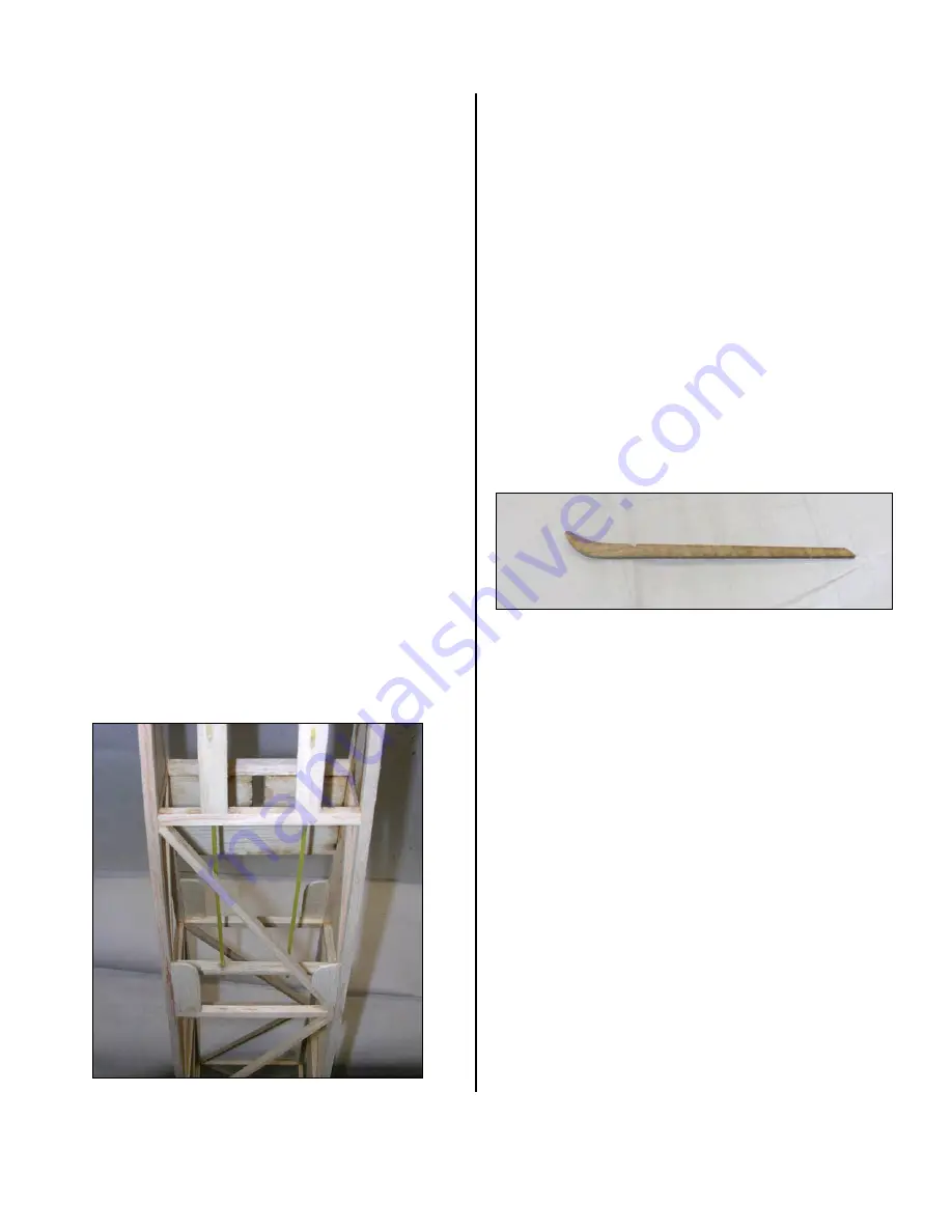
TAILSKID
I
decided
to
start
making
up
the
tailskid.
It
is
made
up
of
three
pieces
of
1/8
ʺ
laser
cut
lite
ply
that
are
glued
together
and
sanded
smooth.
The
front
edge
then
gets
a
piece
of
1/16
ʺ
music
wire
glued
to
the
front
edge
to
stiffen
the
skid
and
make
it
a
bit
more
wear
resistant.
I
have
not
added
the
music
wire
reinforcement
yet.
It
is
important
that
the
tailskid
be
glued
up
accurately
and
strongly
as
it
is
used
to
support
the
rudder
hinge
tube
later
on.
Once
the
tailskid
is
glued
up
it
is
reinforced
on
its
leading
edge
with
a
piece
of
1/16
ʺ
or
so
music
wire
to
strengthen
the
skid
and
to
provide
a
wear
surface.
The
wire
is
bent
to
follow
the
contour
of
the
leading
edge
of
the
skid
and
then
it
is
epoxied
in
place.
HATCH
The
bottom
front
section
of
the
fuselage
between
the
forward
LG
mount
and
the
firewall
is
covered
with
a
piece
of
laser
cut
1/32
ʺ
aircraft
ply.
The
design
calls
for
this
to
be
a
hatch
but
after
looking
things
over
I
decided
that
it
was
not
necessary
due
to
the
large
cockpit
opening
and
the
large
hatch
on
the
bottom
of
the
fuselage
between
the
forward
and
rear
landing
gear
wires.
So
I
decided
to
glue
the
ply
in
place
permanently.
It
could
be
made
into
a
hatch
easily
if
you
decide
it
is
needed.
After
gluing
the
bottom
piece
in
place
I
added
the
top
fuselage
decking.
It
is
also
made
from
a
piece
of
laser
cut


