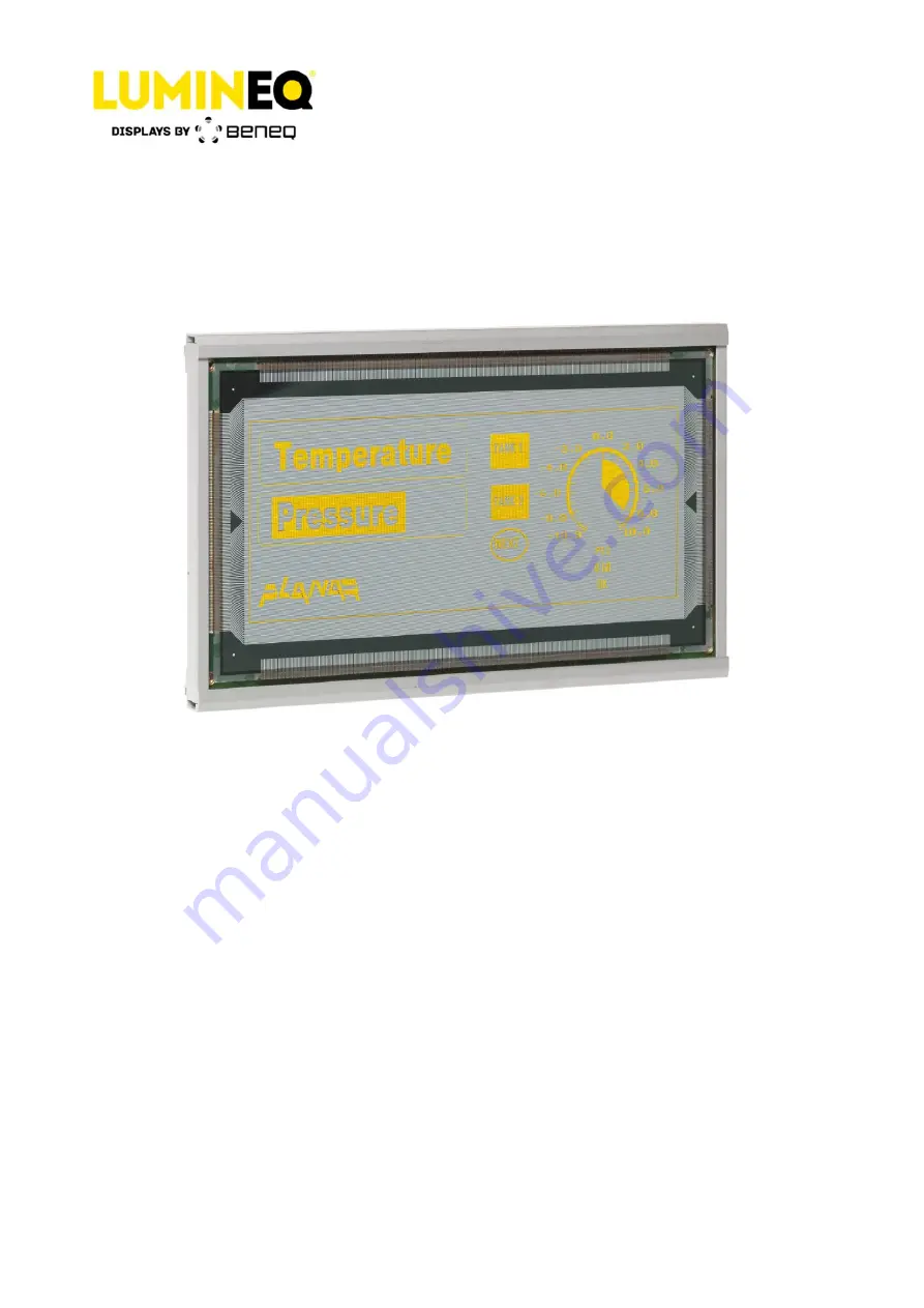
beneq Lumineq EL512.256-H3 Series Operation Manual Download Page 1


EL512.256-H3 Series 
TFEL Display 

Operation Manual 


Beneq Oy 


Olarinluoma 9


Tel. +358 9 7599 530


VAT ID FI19563372


FI-02200 Espoo


Fax +358 9 7599 5310


www.beneq.com


Finland


[email protected]


www.lumineq.com


Date: February 13, 2017


Document number: ED000818C


Page | 1 


EL512.256-H3 Series 

Operation Manual 


Summary of Contents for Lumineq EL512.256-H3 Series

Page 1: ...nual Beneq Oy Olarinluoma 9 Tel 358 9 7599 530 VAT ID FI19563372 FI 02200 Espoo Fax 358 9 7599 5310 www beneq com Finland lumineq beneq com www lumineq com Date February 13 2017 Document number ED000818C Page 1 EL512 256 H3 Series Operation Manual ...

Page 2: ...nding 6 3 7 Connectors 6 3 8 Input specifications 7 4 Display features 8 4 1 Video data input 8 4 2 Two bits parallel data 8 4 3 Display enable 8 4 4 Brightness control 8 4 5 Low power mode 8 4 6 Self test 9 5 Installation and handling 9 5 1 Video input timing 10 5 2 Setup and hold timing 11 6 Operational specifications 12 6 1 Environmental 12 6 2 Reliability 12 6 3 Safety 12 6 4 Optical 13 6 4 1 ...

Page 3: ...1 30 VDC power input and four basic input signals to operate Video Data or pixel information Video Clock pixel clock or dot clock Horizontal Sync Vertical Sync 2 EL technology Figure 1 EL technology A display consists of an electroluminescent glass panel and a mounted circuit board with control electronics The TFEL glass panel is a solid state device with a thin film luminescent layer sandwiched b...

Page 4: ... Signal Symbol Description J1 Data power input connector 1 2 Voltage Vcc2 Supply voltage 11 V 30 V converted to required internal high voltages see J2 3 4 Voltage Vcc1 Supply voltage 5 V for the logic see J2 5 Reserved Reserved do not connect 6 8 10 Ground GND Signal return 7 Two bit data TVID Second data input for 2 bit parallel mode The TVID input is for odd columns and the VID for even ones 9 V...

Page 5: ...consumption of the display is lowered to the LOWPWR values if the _LOWPWR is low internally pulled high if left disconnected 6 Enable ENABLE The operation of the display unit is disabled if the ENABLE input is low internally pulled high if left disconnected J3 Optional control input connector 1 Luminance Pot 1 LUMPOT1 Input for external luminance control see page 8 Can be left disconnected 2 Lumin...

Page 6: ...nput for external luminance control The signals on J2 and J3 that are not used can be left disconnected 3 6 Optional grounding In order to improve the EMC properties of the display system there is an option for the customer to tie together the signal ground of the display and the chassis of the user device For this purpose the four corner mounting nuts are each connected to the signal ground with ...

Page 7: ... 1 and 2 are set 3 8 Input specifications Table 4 Input specifications Parameter Symbol Min Typ Max Absolute min max Logic input HIGH 2 V Vcc1 0 5 V abs max Logic input LOW 0 8 V 0 5 V abs min Logic supply voltage Vcc1 4 75 V 5 0 V 5 25 V 6 V abs max Logic supply current at 5 V Icc1 0 2 A Display Supply voltage Vcc2 11 V 30 V 33 V abs max Supply current at 12 V Icc2 0 5 A 0 9 A Supply current at 1...

Page 8: ... the data for the even columns at VID J1 pin 15 The two bits parallel mode is selected by removing the jumper 2 of the pin strip PS1 4 3 Display enable The display can be totally shut off for screen save or power reduction by a LOW sate in the ENABLE control input J2 pin 6 When disabled the display stops scanning and only the DC DC converter remains functional lowering the power consumption to bel...

Page 9: ...nt application of static charges on the display from the operator or tools The display is made of glass material and should be handled with proper care Do not drop the display or allow hard objects to strike its surface NOTE For trouble free data transfer a maximum cable length of 300 mm 12 in from data transmitter to display input connector is recommended If longer cables up to 2 m 80 in length a...

Page 10: ...2017 Document number ED000818B Page 10 Figure 3 Video input timing 5 1 Video input timing Table 5 Video input timing Description Min typ Max Unit T1 Vertical Front Porch 1 100 µs T2 VS HIGH LOW time 2 1 tVCLK T3 Vertical Period 256 tHS T1 VS frequency 70 75 Hz Description Min Typ Unit T4 HS setup to VS 1 tVCLK T5 HS hold from VS 3 µs T6 HS Low Time 3 4 tVCLK T7 HS High Time 4 512 512 tVCLK T8 HS p...

Page 11: ...000818B Page 11 Notes 1 This time is needed to display the last row and to change the frame 2 Only rising edge is used 3 Video Clock VCLK should be kept running 4 The values for two bit parallel mode are 256 256 tVCLK The number of VCLK pulses during HS high time should be even 5 2 Setup and hold timing Figure 4 Setup and hold timing Table 6 Setup and hold timing Symbol Description Min Max tVCLK V...

Page 12: ...C 65 C no permanent damage Test duration 24 h at temperature extremes without condensation Humidity Relative humidity 40 C 93 RH operating IEC 60068 2 78 Damp heat 25 C 55 C 95 RH non operating IEC 60068 2 30 Altitude Operating 15 000 m 50 000 ft above sea level Vibration 20 500 Hz ASD level 0 05 g2 Hz Random vibration wide band IEC 60068 2 64 Test Fdb Shock Magnitude Duration Number of shocks 100...

Page 13: ...t the center and the four corners of the screen Luminance non uniformity Maximum 35 1 min luminance max luminance x 100 Maximum difference between any two of five points center and four corners Luminance variation time Maximum 20 10 000 h Luminance variation temperature Typical 10 over 25 C 65 C range Maximum 15 Viewing angle Minimum 160 6 4 2 Optional filter For the best overall optical performan...

Page 14: ...Display external dimensions Height 136 mm 5 35 in Width 233 mm 9 17 in Depth 16 5 mm 0 65 in Weight 400 g 14 oz 7 2 Display viewing area characteristics Table 10 Display viewing area characteristics Active area millimeters inches height 97 5 3 84 width 195 1 7 68 Pixel pitch millimeters inches height 0 381 0 015 width 0 381 0 015 Pixel size millimeters inches height 0 25 0 01 width 0 25 0 01 Pixel...

Page 15: ...l 358 9 7599 530 VAT ID FI19563372 FI 02200 Espoo Fax 358 9 7599 5310 www beneq com Finland lumineq beneq com www lumineq com Date February 13 2017 Document number ED000818B Page 15 Figure 5 Viewing area characteristics Figure 6 Front view without mounting frame standard ...

Page 16: ...eq Oy Olarinluoma 9 Tel 358 9 7599 530 VAT ID FI19563372 FI 02200 Espoo Fax 358 9 7599 5310 www beneq com Finland lumineq beneq com www lumineq com Date February 13 2017 Document number ED000818B Page 16 Figure 7 Back and side views dimensions in mm ...

Page 17: ...a 9 Tel 358 9 7599 530 VAT ID FI19563372 FI 02200 Espoo Fax 358 9 7599 5310 www beneq com Finland lumineq beneq com www lumineq com Date February 13 2017 Document number ED000818B Page 17 Figure 8 Back and side views with FRA aluminum mounting frame dimensions in mm ...

Page 18: ...ma 9 Tel 358 9 7599 530 VAT ID FI19563372 FI 02200 Espoo Fax 358 9 7599 5310 www beneq com Finland lumineq beneq com www lumineq com Date February 13 2017 Document number ED000818B Page 18 Figure 9 Back and side views with FRB steel mounting frame dimensions in mm ...

Page 19: ...in the goods are not within this warranty Repair or replacement of goods is seller s sole obligation and buyer s exclusive remedy for all claims of defects If that remedy is adjudicated insufficient Seller shall refund buyer s paid price for the goods and have no other liability to buyer All warranty repairs must be performed at seller s authorized service center using parts approved by seller Buy...

Page 20: ...n support of EU directive 2011 65 EU the Restriction of Hazardous Substances commonly known as RoHS II or RoHS Recast which compared to RoHS keeps the restrictions on the original six hazardous substances including lead Pb in electronic equipment It also expands these restrictions to previously exempted categories including medical devices and monitoring and control instruments Beneq part number w...

Reviews: