27
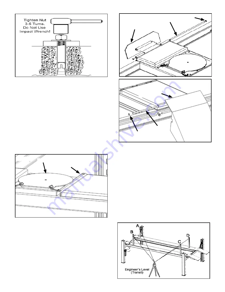
6. With the Shims and Anchor Bolts in place, tighten Nut
three to five turns past finger tight. Do not use an Impact
Wrench for this procedure. (See Fig. 14.6)
IMPORTANT !
If Anchor Bolts do hold when torqued to required
amount, concrete must replaced. Saw cut and
remove 24” x 24” square area each Column base
then re-pour with reinforced 2500 PSI concrete to a
depth of six inches minimum, keying new concrete
under existing floor.
STEP 15
(Installing Accessories)
1. Place the Turnplates in the Turnplate pockets. Insert
the Rollback Spacer Bars between the Turnplate and ris-
ers as needed for alignment procedures. (See Fig 15.1)
2. Install the Front Tire Stops using the Hinge Pins and
rotor-clips as shown. (See Fig. 15.2)
3. Install the Drive-Up Ramps using the Hinge Pins and
rotor-clips as shown. (See Fig. 15.3)
STEP 16
(Leveling / Sychronizing)
1. Using an Engineer’s Automatic Level (transit), locate
the Level, at a convenient location in the shop that allows
an unobstructed view of all four corners of the runways.
2. Follow the Level manufacturer’s instructions for proper
setup of the Level. Be sure it is adjusted level in all direc-
tions.
3. Raise the lift approximately 30”- 40”. Then lower the
lift until all Primary Safeties are completely resting on the
same Safety Ladder position on all Safety Ladders.
4. Place a Level target on the right/front corner of the
ramp. (See Fig. 16.1)
Fig 14.6
Fig 15.2
Hinge Pin
Rotor Clip
Tire Stop
Fig 15.1
Turnplate
Rollback
Spacer
Fig 15.3
Hinge Pin
Drive-Up
Ramp
Fig 16.1
Rotor Clip


