BENDIX AD-4 Manual Download Page 5

5

2. Check mounting bolts for tightness. Retorque to 270-

385 inch pounds.

3. Perform the Operation & Leakage Tests listed in this

publication.

Every 10,800 hours or 300,000 miles or 36 months:

1. Rebuild the air dryer including the desiccant cartridge.

Note: The desiccant change interval may vary from vehicle
to vehicle. Although typical desiccant cartridge life is three
years, many will perform adequately for a longer period of
time. In order to take maximum advantage of desiccant life
and assure that replacement occurs only when necessary,
it is important that Operation & Leakage Tests be performed.

WARNING!

This air dryer is intended to remove moisture and other
contaminants normally found in the air brake system.
Do not inject alcohol, anti-freeze, or other de-icing
substances into or upstream of the air dryer.  Alcohol
is removed by the dryer, but reduces the effectiveness
of the device to dry air.  Use of other substances can
damage the air dryer and may void the warranty.

OPERATION & LEAKAGE TESTS

1. Test the outlet port check valve assembly by building

the air system to governor cut-out and observing a test
air gauge installed in the supply reservoir. A rapid loss of
pressure could indicate a failed outlet port check valve.
(Note: Purge valve will be open when governor cut-out
pressure is reached. Allow 45 seconds after governor
cut-out occurs to complete the purge cycle before testing
the check valve.) Coat the exhaust with a soap solution.
Leakage should not exceed a 1" bubble in 1 second.

2. Check for excessive leakage around the purge valve.

With the compressor in loaded mode (compressing air),
apply a soap solution to the purge valve housing
assembly exhaust port and observe that leakage does
not exceed a 1" bubble in 1 second. If the leakage
exceeds the maximum specified, service the purge valve
housing assembly.

3. Close all reservoir drain cocks. Build up system pressure

to governor cut-out and note that AD-4

 air dryer purges

with an audible escape of air. “Fan” the service brakes
to reduce system air pressure to governor cut-in. Note
that the system once again builds to full pressure and is
followed by an AD-4

 air dryer purge.

4. Check the operation of the safety valve by pulling the

exposed stem while the compressor is loaded
(compressing air). There must be an exhaust of air while
the stem is held and the valve should reseat when the
stem is released.

5. Check all lines and fittings leading to and from the air

dryer for leakage and integrity.

6. Check the operation of the end cover heater and

thermostat assembly during cold weather operation as
follows:

A. Electric Power to the Dryer

With the ignition or engine kill switch in the ON
position, check for power at the dryer’s electrical
terminal using a voltmeter or test light. On a single
terminal AD-4

 air dryer’s disconnect the lead wire

at the end cover terminal post. Place the test leads
on the lead wire and a GOOD vehicle ground. On
dual terminal AD-4

 air dryer’s disconnect both lead

wires at the end cover terminal posts. If there is no
voltage indicated, look for a blown fuse, broken wires,
or corrosion in the vehicle wiring harness. Check to
see if a good ground path exists.

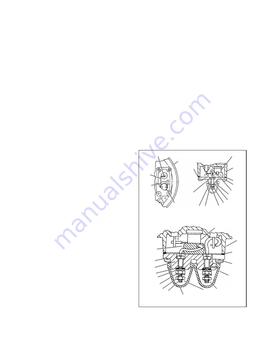
B. Thermostat and Heater Operation

Turn off the ignition switch and cool the end cover
assembly to below 40 degrees Fahrenheit. Using an
ohmmeter, check the resistance between the
electrical terminal and the metal end cover (see Figure
5). (Note: On the dual terminal end cover, check the
resistance between the two terminals.) The

FIGURE 5 - AD-4

 AIR DRYER SINGLE AND DUAL

TERMINAL THERMOSTAT ASSEMBLIES

DUAL WIRE SYSTEM

BOOT

7

10

9

1

11

8

6

1

CONNECTIONS FOR POWER

AND INSULATED RETURN

BOOT

3

2

4

5

BOLD NUMBERS ARE ITEMS IN MAINTENANCE KITS

SINGLE WIRE SYSTEM

1

9

8

1

9

2

1

4

6

11

7

10

THERMOSTAT

COVER

5

3

A

B

HEATER POST

Summary of Contents for AD-4

Page 1: ...valve assembly a safety valve purge valve mechanism a cast in heater element with a replaceable thermostat assembly and three threaded air connections The three air connections are identified with em...

Page 2: ...m the air flows into the desiccant cartridge Once in the desiccant cartridge air first flows through an oil separator which removes water in liquid form as well as oil oil vapor and solid contaminants...

Page 3: ...r flows from the purge volume through the desiccant cartridge purge orifice and into the desiccant drying bed Pressurized air from the purge volume expands after passing through the purge orifice its...

Page 4: ...ement that does not allow the compressor to load and unload compressing and non compressing cycle in a normal fashion Check for high air system leakage If the vehicle vocation has changed it may be ne...

Page 5: ...rvice the purge valve housing assembly 3 Close all reservoir drain cocks Build up system pressure to governor cut out and note thatAD 4 air dryer purges with an audible escape of air Fan the service b...

Page 6: ...onents of the air dryer use only genuine Bendix parts For ease in servicing the AD 4 air dryer desiccant cartridge assembly it is recommended that the air dryer be removed from the vehicle MAINTENANCE...

Page 7: ...SICCANT CARTRIDGE CAP SCREW LOCKWASHER SEALING RING SEALING RING END COVER HEATER VOLTAGE SHOWN SUPPLY PORT CONTROL PORT SPRING O RING PURGE PISTON SPECIAL WASHER EXHAUST DIAPHRAGM DELIVERY PORT BRACK...

Page 8: ...ompressor discharge line may still contain residual pressure 3 Identify and disconnect the three air lines from the end cover and note the position of end cover ports relative to the vehicle 4 Pull bo...

Page 9: ...assembly coat all o rings o ring grooves and bores with a generous amount of barium base lubricant Important Note The single exception to prelubrication is the sealing ring between the desiccant cartr...

Page 10: ...THERMOSTAT ASSEMBLY Refer to Figure 5 1 Cut uninsulated lead of new thermostat 1 at Point A 2 Install thermostat in end cover pocket and position uninsulated leads next to each other 3 Using a solderi...

Page 11: ...n 9 000 cu in Standard AD 4 Air Dryer 9 000 12 500 cu in Extended Purge AD 4 Air Dryer Greater than 12 500 cu in Contact Bendix Rep or Bendix Engineering RE INSTALLATION 1 Install the assembled AD 4 a...

Page 12: ...an be of two types The one described above or a single piece right angle bracket See Figure 7 To install the single piece lower mounting bracket remove and discard two of the bolts and nuts that retai...

Page 13: ...ice perform the following tests 1 Close all reservoir drain cocks 2 Build up system pressure to governor cut out and note that the AD 4 air dryer purges with an audible escape of air 3 Fan the service...

Page 14: ...hether air pressure loss is shown on dash gauge s Pressure loss shown on gauges is caused by service brake system or component leakage Pressure loss NOT SHOWN on gauges is caused by supply system or c...

Page 15: ...n either test repair or replace governor 4 Test compressor unloader leakage Drain all air pressure from system and remove the governor from the compressor Temporarily plug the governor unloader port o...

Page 16: ...r proper operation Make certain Holset ECON is not used with the drop in version of the air dryer if so remove and retest B Leaking purge valve in air dryer end cover control side C Holset E type comp...

Page 17: ...sories it is necessary to determine that during normal daily operation the compressor should recover from governor cut in to governor cut out usually 100 psi to 120 psi in 90 seconds or less at engine...

Page 18: ...let line size is 3 4 ID Maximum restriction requirement for compressors is 25 inches of water Check the engine air filter and service if necessary if possible check the air filter usage indicator Poor...

Page 19: ...brake charging system is functioning normally 3 Oil present at air dryer purge exhaust or cartridge during maintenance A Check to determine if air is reaching supply reservoir Inspect for kinked tubin...

Page 20: ...rt of governor D Test heater and thermostat as described in Preventative Maintenance Section E See Symptom 1 E Excessive system leakage F Purge valve stays open supply air leaks to control side F Repa...

Page 21: ...this data sheet A A slight pinging sound may be heard during system build up when a single cylinder compressor is used If this sound is deemed objectionable it can be reduced substantially by increas...

Page 22: ...ction loggers concrete mixer dump truck fire truck e g Line haul single trailer w o air suspension air over hydraulic brakes e g Line haul single trailer with air suspension school bus e g City transi...

Page 23: ...only encountered complaints CONVENTIONAL SUPPLY SYSTEM INTEGRAL PURGE AIR DRYER HOLSET TYPE E QE COMPRESSOR WITH ECON VALVE FRONT REAR DASH GAUGE STANDARD SINGLE CHECK VALVE LOW PRESSURE INDICATOR SUP...

Page 24: ...24 BW1450 2004 Bendix Commercial Vehicle Systems LLC All rights reserved 10 2004 Printed in U S A...

Reviews: