background image

8

VG12_D00032_03_M_XXEN/01.2019

3.  System description

3.1   Protective measures for mobile generators

The VG12 safety distributor is intended for the practical implementation of the protec-
tive measure "Protective separation with insulation monitoring and disconnection" 
specified in section 551.4.4.2 of the standard DIN VDE 0100-551. 

The voltage supply is designed in a way that protective separation is realised with more 
than one load. The continuously measuring ISOMETER® switches off the mains voltage 
if the value falls below the response value. This results in the following characteristics:

 

No earth spike

 

High-resistance insulation faults are detected immediately. When reaching the 
response value, the socket-outlets of the VG12 are switched off.
(DIN VDE 0100-410, Annex C3)

 

Suitable only for operation and monitoring by electrically skilled or instructed 
persons.

 

The exposed conductive parts of the whole generator circuit must be connected 
by insulated, unearthed protective equipotential-bonding conductors PA (see 
schematic wiring diagram on 

Page 15

). 

Such conductors must not be connected to the protective conductors or exposed 
conductive parts of other circuits or to any other conductive parts.

An ISOMETER® measures the sum of all insulation faults in the system, i.e. the absolute 
insulation value.

Page 21

 provides a list of all relevant standards.

3.2   Prerequisites for use 

The protective measure "Protective separation with insulation monitoring and discon-
nection" avoids hazards from indirect contact with parts carrying voltage due to faults 
in the basic insulation of the circuit.

 

The power generator must supply a single-phase AC voltage of 230 V. Tolerances 
according to IEC 38 are permissible. Higher voltages may destroy components of 
the safety distributor. Hence, the protective function may be disabled.

 

The maximum load current must not exceed 16 A. Higher load currents may 
destroy the contacts of the connection plug of the VG12 safety distributor and 
thus disable the protective function.

Summary of Contents for B980853

Page 1: ...EN Manual VG12 Safety distributor for mobile power generators ready for connection VG12_D00032_03_M_XXEN 01 2019...

Page 2: ...o KG P O Box 1161 35301 Gr nberg Germany Londorfer Stra e 65 35305 Gr nberg Germany Tel 49 6401 807 0 Fax 49 6401 807 259 E mail info bender de www bender de Bender GmbH Co KG All rights reserved Repr...

Page 3: ...7 2 4 General safety instructions 7 3 System description 8 3 1 Protective measures for mobile generators 8 3 2 Prerequisites for use 8 3 3 Functional description 9 3 3 1 Display and operating element...

Page 4: ...Table of Contents 4 VG12_D00032_03_M_XXEN 01 2019 6 Technical data 19 6 1 Standards and certifications 21 6 2 Ordering details 22 6 3 Other safety distributors 22 INDEX 23...

Page 5: ...ave any questions please do not hesitate to contact us In this case please refer to our service www bender de en service support downloads 1 2 Explanation of symbols and notes The following symbols to...

Page 6: ...d in order to be able to apply the protective measure 2 2 Work activities on electrical installations Only electrically skilled persons are permitted to carry out the work necessary to install commiss...

Page 7: ...anger safety Do not make any unauthorised changes and only use replacement parts and opti onal accessories purchased from or recommended by the manufacturer of the devices Failure to observe this requ...

Page 8: ...whole generator circuit must be connected by insulated unearthed protective equipotential bonding conductors PA see schematic wiring diagram on Page 15 Such conductors must not be connected to the pro...

Page 9: ...ects the VG12 safety distributor to the power generator The VG12 safety distributor contains an insulation monitoring device in accordance with EN 61557 8 It is an actively measuring ISOMETER type IR4...

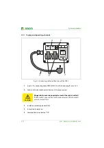
Page 10: ...tlets If both sockets are used the total nominal current of both sockets must not exceed 16 A 3 Insulation monitoring device IR423 4 Instruction for daily test 5 Combined test reset button T R Achtung...

Page 11: ...p if the value falls below the response value Ran2 Alarm 2 prewarning 4 The test button T is intended for the daily test of the safety distributor After pressing it AL1 and AL2 light up 5 The insulati...

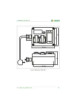
Page 12: ...they are not destroyed by the typical vibrations of the power generator Avoid sharp edges and corners Secure the mounting screws via lock washers spring washers or the like 4 1 1 Dimension diagrams Fi...

Page 13: ...Installation and connection 13 VG12_D00032_03_M_XXEN 01 2019 Fig 4 2 Dimensions of the VG12 130 180 mm 96 ca 40 mm 163 mm 113...

Page 14: ...ectrically skilled persons WARNING Danger due to freely accessible generator socket outlets Use the socket outlets of the VG12 safety distributor only Any other socket outlets of the power generator m...

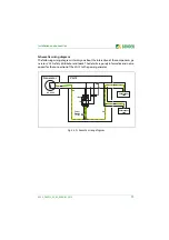
Page 15: ...rms you about the interaction of the components ge nerator VG12 safety distributor and loads The details are purely informative and not re quired for the connection of the VG12 to the power generator...

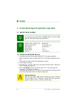
Page 16: ...t reset button T R of the VG12 A short time later tES appears on the display for a few seconds In the following the alarm LEDs AL1 and AL2 light up and the VG12 disconnects all poles of the safety soc...

Page 17: ...the VG12 safety distributor 3 Press the combined test reset button T R of the VG12 for 3 s A short time later tES appears on the display for a few seconds In the following the alarm LEDs AL1 and AL2...

Page 18: ...reset button T R was pressed deliberately or acci dentally Press the combined test reset button T R for 1 s LEDs AL1 AL2 light up no loads connected Insulation fault power generator Turn off power ge...

Page 19: ...elay ton 0 99 s 0 s Measuring circuit Measuring voltage Um 12V Measuring current Im at RF 0 200 A Internal resistance DC Ri 62 k Impedance Zi at 50 Hz 60 k Permissible extraneous DC voltage Ufg DC 300...

Page 20: ...60721 3 3 3M4 Transport IEC 60721 3 2 2M2 Long term storage IEC 60721 3 1 1M3 Vibration resistance acc to IEC 60068 2 6 DIN rail 3 g 30 150 Hz Screw mounting 6 g 30 150 Hz Connection Socket outlets In...

Page 21: ...ecial installations or locations Construction and demolition site installations DIN VDE 0100 100 VDE 0100 100 Low voltage electrical installations Part 100 Application area purpose and principles DVGW...

Page 22: ...iented protective measures Protective separation with insulation monitoring and shutdown Type Nominal voltage Un Order number VG12 Safety distributor for mobile power generators ready for connection A...

Page 23: ...ional test before first use 16 H How to use this manual 5 I Installation 12 Intended use 6 O Ordering details 22 Other safety distributors 22 R Regular tests 18 S Safety instructions device specific 7...

Page 24: ...ives and bendersystembau archives Bender GmbH Co KG P O Box 1161 35301 Gr nberg Germany Londorfer Stra e 65 35305 Gr nberg Germany Tel 49 6401 807 0 Fax 49 6401 807 259 E mail info bender de www bende...

Reviews: