System description
11
In general, an operation of the IR423 is not required. Thus, the description of the opera-
ting elements is only informative.
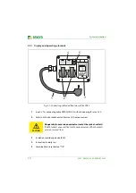
Fig. 3.2: Front view of the IR423
1
POWER ON LED
2
The alarm LED "AL1" lights up if the value falls below the response value
R
an1
(Alarm 1) (prewarning).
3
The alarm LED "AL2" lights up if the value falls below the response value
R
an2
(Alarm 2) (prewarning).
4
The test button "T" is intended for the daily test of the safety distributor.
After pressing it, "AL1" and "AL2" light up.
5
The insulation monitoring device is reset by pressing the reset button "R".
The alarm LEDs "AL1" and "AL2" go out.
6
The menu/enter button is intended for accessing the menu operation,
choosing functions and changing values. The button is not required for
normal operation!
7
Display for indicating the insulation value and for navigating in the menu
1 2 3
4 5 6
MENU
7


