Installation and connection
15
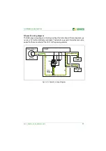
Schematic wiring diagram
The following wiring diagram informs you about the interaction of the components ge-
nerator, VG12 safety distributor and loads. The details are purely informative and not re-
quired for the connection of the VG12 to the power generator.
Fig. 4.3: Schematic wiring diagram
PA
Test/
Reset
„T/R“
IR423
< R
PA
VG12
Generator
AC 230 V
Verbraucher/
Load
Verbraucher/
Load


